SE

This educational application supplements, but does not replace, the official AASHTO LRFD Bridge Design Specifications, applicable state DOT manuals, project specifications, and professional engineering judgment.

Engineering Stories

The failures that wrote the code

Eight narratives — one per code lesson. Each includes a timeline, engineering root cause, AASHTO articles the failure produced, and a link to the chapter that teaches the underlying limit state.
Reading mode
100%

Tacoma Narrows Bridge (Galloping Gertie)

7 November 1940 · Puget Sound, WA

Long-span plate-girder-stiffened suspension (2,800 ft main span)
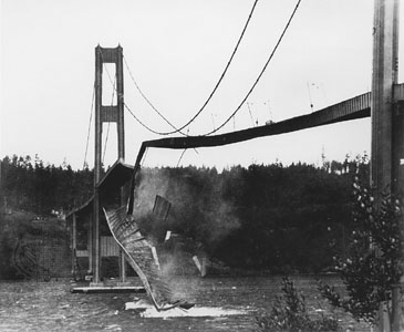
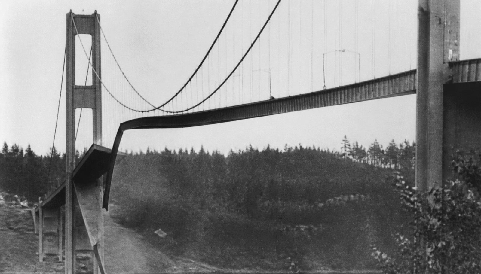
Tacoma Narrows Bridge (Galloping Gertie) — Puget Sound, WA

7 Nov 1940 — the 39-ft-wide, 8-ft-deep plate-girder deck in fully developed torsional flutter. The two curbs are at radically different elevations: the section is rotating about its centerline, not bending.

Photo: Washington State Archives / Wikimedia Commons (public domain)

Timeline

  1. 1 Jul 1940

    Bridge opens; noticeable vertical oscillations from day one.

  2. 7 Nov 1940 · 10:00

    Wind ~42 mph; motion transitions from vertical to torsional flutter.

  3. 11:00

    Torsional amplitude exceeds 45°; deck twists in opposing directions between towers.

  4. 11:10

    Suspender cables at midspan fail; central span collapses. No human fatalities (one dog).

Engineering root cause

Aeroelastic torsional flutter of an unusually slender H-section deck. Bluff cross-section shed vortices that resonated with the fundamental torsional mode.

Forensic findings

  • Deck slenderness: L/d = 2,800/8 = 350, versus ≈ 85 for the Golden Gate. The section had almost no torsional stiffness (open H-section, GJ ≈ 0).
  • The solid stiffening girders acted as a bluff body. Vortices shed at a frequency that locked in with the first antisymmetric torsional mode (0.2 Hz) — classic single-degree-of-freedom flutter, not simple resonance.
  • Critical flutter wind speed was later back-computed at ≈ 35–42 mph. The design wind pressure had been treated as a static 30 psf — a strength check with no aerodynamic content whatsoever.
  • Failure initiated when a north-side cable band slipped at midspan, converting the symmetric suspension geometry into an asymmetric one and removing the last torsional restraint.

What it changed in the code

Every long-span suspension/cable-stayed deck now undergoes wind-tunnel section-model testing; AASHTO requires aeroelastic evaluation and requires dynamic analysis for flexible structures.

What you do differently today

  • Section-model wind-tunnel testing is mandatory for any deck with a span-to-depth ratio above ~150 or a fundamental frequency below 1 Hz.
  • Use a torsionally closed section (box girder) or add an open truss deck with grating to bleed pressure — both raise the critical flutter speed.
  • Check flutter, vortex-induced vibration, galloping and buffeting separately; passing one does not imply the others.
  • AASHTO §3.8.3 requires that aeroelastic instability not occur below the design wind speed with a margin; §C4.6.5 governs the dynamic model.
Silver Bridge

15 December 1967 · Point Pleasant, WV — Kanawha River

Eyebar-chain suspension (700 ft main span, non-redundant)

46 fatalities
Chapter 17
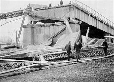
Silver Bridge — Point Pleasant, WV — Kanawha River

The Silver Bridge main span in the Ohio River, December 1967. The eyebar chain — visible as scattered links — carried the entire deck with only two bars per joint.

Photo: U.S. federal government / Wikimedia Commons (public domain)

Timeline

  1. 17:00 rush hour

    Chain-link C13N eyebar fails in a single grain-boundary crack.

  2. 17:04

    Load redistributes onto its non-redundant twin; north tower loses eastbound chain support.

  3. 17:05

    Entire main span drops into the Ohio River. 46 deaths.

Engineering root cause

Stress-corrosion cracking initiated at a 0.1-inch flaw in the eye of a heat-treated 1035 steel eyebar. Non-redundant chain: one eyebar's failure = collapse.

Forensic findings

  • The chain used heat-treated 1035 carbon-steel eyebars at ~50 ksi working stress. Each joint had only two bars: loss of one bar is loss of the joint.
  • Crack initiation was a 0.12-in-deep stress-corrosion flaw at the bore of eyebar 330 (joint C13N), grown over 40 years by hydrogen-assisted cracking in a crevice that could not be seen or cleaned.
  • Fracture toughness of the 1927 steel at the 0 °F service temperature was ≈ 25 ksi·√in — well inside the brittle regime. The critical crack size was smaller than the resolution of visual inspection.
  • Total elapsed time between fracture of the first eyebar and full collapse: under 60 seconds. There was no ductile warning of any kind.

What it changed in the code

Congress passed the Federal-Aid Highway Act of 1968 creating the NBIS. AASHTO fracture-control provisions () codified FCM (Fracture-Critical Member) inspection intervals.

What you do differently today

  • Fracture-Critical Member (FCM) inventories and hands-on arm's-length inspection at 24-month intervals — 23 CFR 650 Subpart C, born directly from this collapse.
  • AASHTO §6.6.2 sets Charpy V-notch toughness by temperature zone and by whether the member is fracture-critical.
  • Prefer internally redundant or load-path-redundant details: four eyebars per joint instead of two changes the consequence of a single fracture entirely.
  • Where non-redundant tension members must be used, require redundancy analysis per the AASHTO Guide Specifications for Internal Redundancy of Mechanically Fastened Built-Up Steel Members.

I-35W Mississippi River Bridge

1 August 2007 · Minneapolis, MN

Steel-deck-truss main span (458 ft, non-load-path-redundant)

13 fatalities
Chapter 11
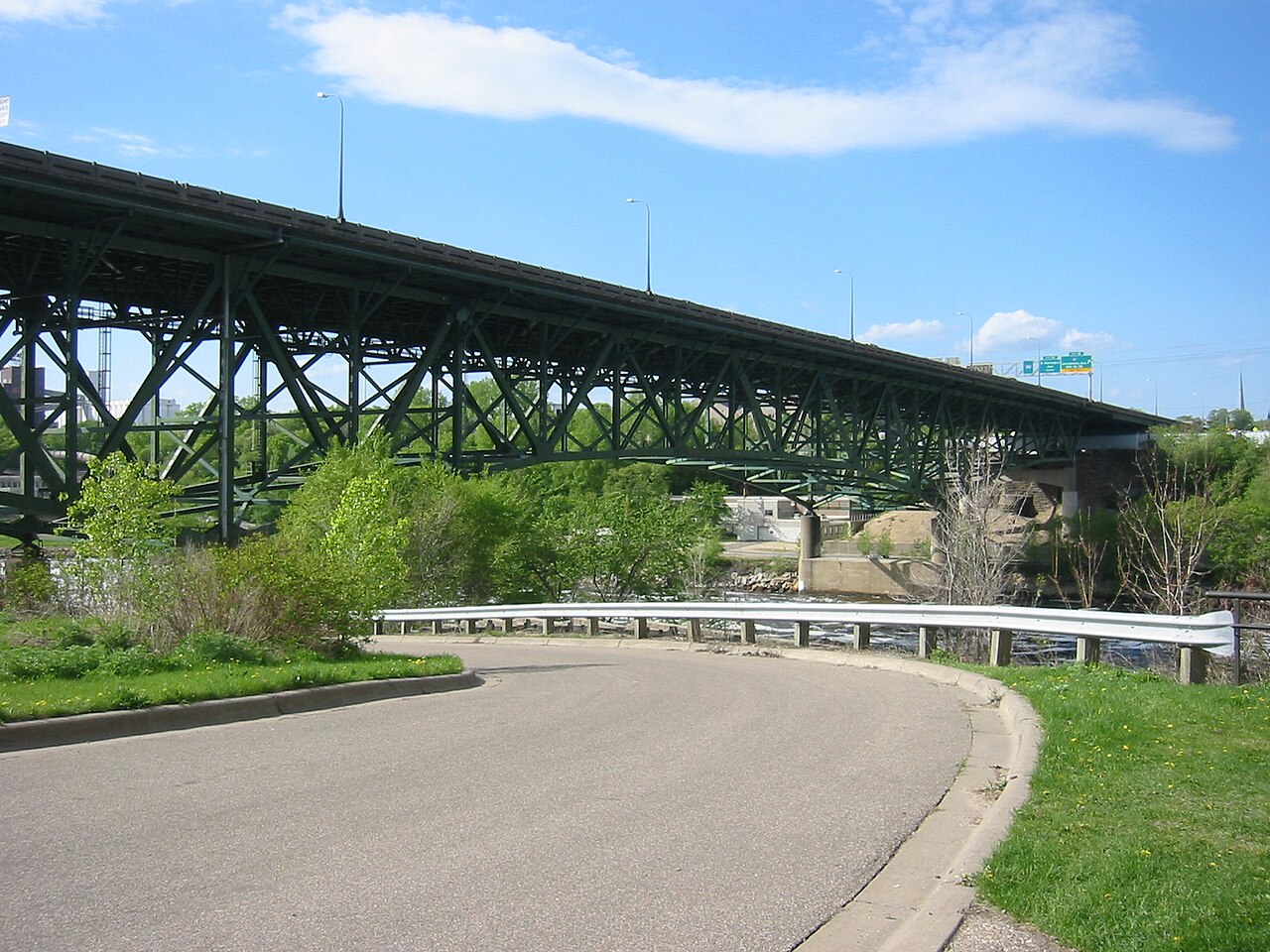
I-35W Mississippi River Bridge — Minneapolis, MN

I-35W main span in the Mississippi, August 2007. The deck truss folded at the U10 node — a half-inch gusset plate carrying a member force that demanded a full inch.

Photo: U.S. Navy / Wikimedia Commons (public domain)

Timeline

  1. 1967

    Bridge designed with 1/2-in U10 (should have been 1 in).

  2. 1998–2007

    Successive deck resurfacings add ~20% dead load; ongoing construction stockpiles 578,000 lb on the deck.

  3. 1 Aug 2007 · 18:05

    U10 gussets yield and buckle; center span collapses within 4 seconds.

Engineering root cause

Design error in gusset-plate thickness (drafting mistake, 1965), latent for 40 years and unmasked by cumulative dead-load additions and construction surcharge.

Forensic findings

  • The U10 were 0.5 in thick; back-analysis showed 1.0 in was required. The error dates from a 1965 design-office calculation that was never independently checked.
  • Demand-to-capacity at U10 under original 1967 loading was already ≈ 1.0 — no margin at all before any later change.
  • Two deck resurfacings (1977, 1998) added roughly 20% dead load; on collapse day 383 tons of construction aggregate, sand and equipment sat directly over U10 and U10′.
  • Failure mode was gusset-plate along the free edge between the U10 diagonal and the lower chord — a stability failure, not a yielding failure, so the plate lost capacity abruptly.
  • Inspection had photographed visible bowing of the U10 plates for years; no procedure required a connection capacity check, so the photographs were filed and not analyzed.

What it changed in the code

NCHRP 12-84 and FHWA gusset-plate guidance mandated back-check of every non-load-path-redundant truss connection. now explicitly checks connections independent of members.

What you do differently today

  • Load rating must include gusset plates as rateable elements (FHWA Gusset Plate Guide, 2009; AASHTO MBE §6A.6.12).
  • Check all six gusset limit states: gross/net section yield, block shear, Whitmore-section yield, gusset buckling on the Whitmore width, shear on critical planes, and fastener capacity.
  • Every added wearing surface, barrier upgrade or utility attachment on a non-redundant truss requires a re-rating — dead load creep is cumulative and silent.
  • Construction staging loads on an in-service bridge require a written analysis and a stated limit, posted for the contractor.

Hoan Bridge Cracking

13 December 2000 · Milwaukee, WI (no collapse)

Continuous steel plate-girder tied arch approach

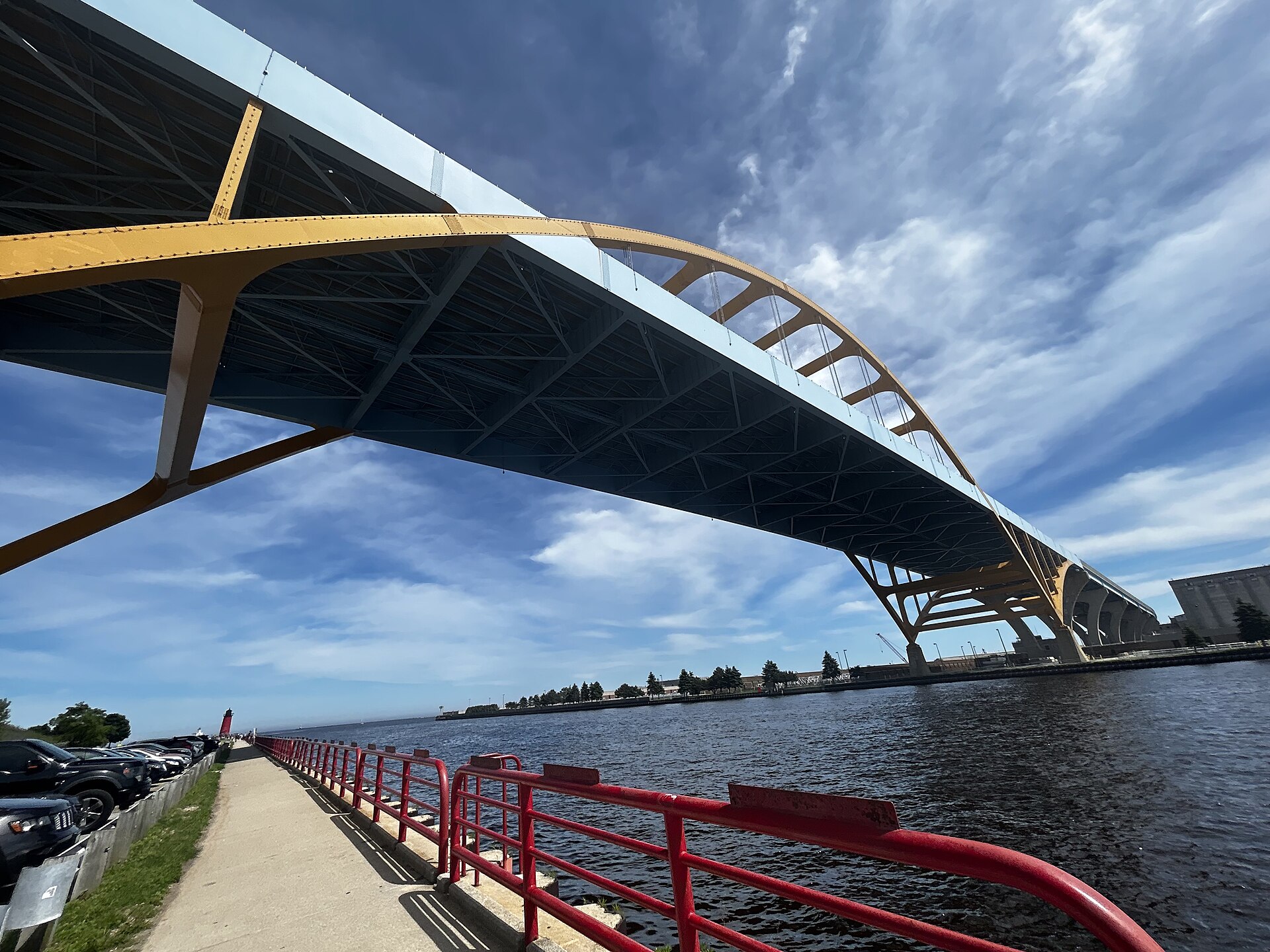
Hoan Bridge Cracking — Milwaukee, WI (no collapse)

The Daniel Hoan Memorial Bridge, Milwaukee. In December 2000 three of its approach girders cracked full-depth overnight — the structure did not fall, and that is exactly why it is worth studying.

Photo: Wikimedia Commons (CC BY-SA)

Timeline

  1. 13 Dec 2000

    Sub-zero temperatures; three girders develop full-depth web-and-flange cracks near a lateral bracing connection.

  2. Days after

    Bridge closed for emergency repair. Cracks propagated from bracing gussets welded directly to the girder tension flange.

Engineering root cause

Constraint-induced fracture at a triaxial-restraint detail — the lateral connection plate fully welded to a stiffener and the tension flange created a fatigue Category E'' hotspot with almost no toughness margin at −20 °F.

Forensic findings

  • The lateral bracing gusset was welded to a transverse stiffener that was in turn welded to the tension flange, producing a fully restrained, triaxially stressed intersection with essentially zero ability to yield.
  • Constraint-induced fracture (CIF) needs three ingredients simultaneously: high restraint, a low-toughness material at service temperature, and a crack-like discontinuity from welding. All three were present.
  • Ambient temperature at the time of cracking was about −20 °F; the flange steel was A36 with no supplemental CVN requirement.
  • Two of the three cracked through the web and both flanges. The span stayed up only because the deck slab and the remaining girder provided an unintended alternate load path.

What it changed in the code

AASHTO now requires web gaps of at least 4 t_w between transverse stiffeners and tension flanges, and FHWA guidance restricts direct-to-flange connection details.

What you do differently today

  • Never weld a lateral connection plate directly to a tension flange; provide the web-gap detail of AASHTO §6.6.1.2.4 (gap ≥ 4 t_w, and typically ≥ 6 in).
  • Screen the existing inventory for CIF-susceptible details — FHWA Technical Advisory T 5140.29 lists the geometries.
  • Specify Zone 2/3 CVN toughness for primary tension components in cold climates; toughness is the only defence once a crack-like flaw exists.
  • Value system redundancy explicitly: the Hoan girders cracked and the bridge survived because a second load path existed. Design that path on purpose, not by accident.

Sunshine Skyway (Summit Venture)

9 May 1980 · Tampa Bay, FL

Steel through-truss cantilever main span

35 fatalities
Chapter 16
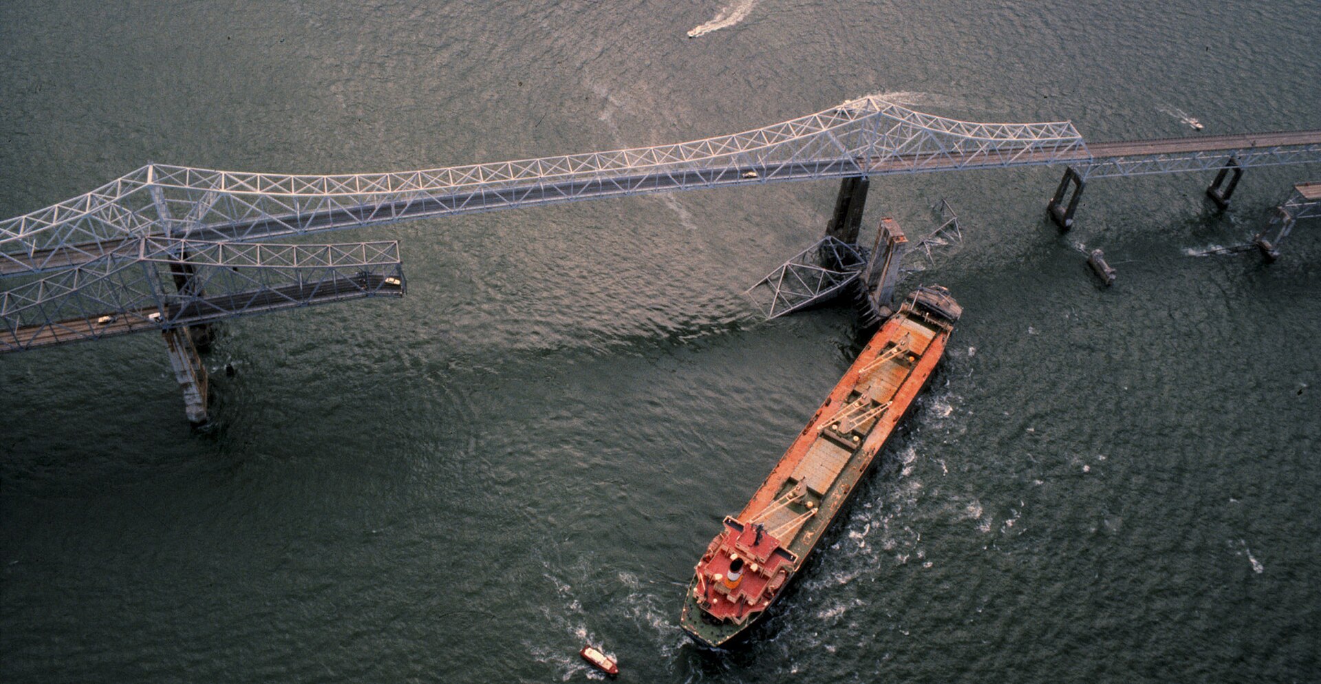
Sunshine Skyway (Summit Venture) — Tampa Bay, FL

9 May 1980 — 1,261 ft of the southbound Sunshine Skyway in Tampa Bay after the bulk carrier Summit Venture struck pier 2S in a blinding squall.

Photo: U.S. Coast Guard / Wikimedia Commons (public domain)

Timeline

  1. 07:33

    Freighter Summit Venture loses radar in a squall and strikes pier 2S.

  2. 07:34

    1,200 ft of southbound superstructure collapses; 35 fatalities including a Greyhound bus.

Engineering root cause

Non-impact-protected pier of a single-line-of-defense truss over a designated navigation channel. Vessel drift and pilot workload during a storm were not part of the 1971 design envelope.

Forensic findings

  • The 1971 design used a nominal static ship-impact force with no consideration of vessel displacement, speed distribution or channel geometry.
  • Summit Venture displaced roughly 35,000 tonnes and was travelling near 8 knots — kinetic energy on the order of 100 MN·m, orders of magnitude beyond the pier's capacity.
  • The pier had no fender, no dolphin and no island protection. Structural collapse and vessel-impact resistance were effectively the same line of defence.
  • The cantilever truss was non-redundant transversely: loss of one pier removed support from three spans at once.

What it changed in the code

AASHTO Guide Specification and Commentary for Vessel Collision Design of Highway Bridges (1991) — later — introduced probabilistic vessel-collision load with dolphin/fender energy-absorption requirements.

What you do differently today

  • AASHTO §3.14 gives a probabilistic method: annual frequency of collapse AF = N · PA · PG · PC, and AF must not exceed 0.0001 for critical bridges (0.001 for regular).
  • Design the pier for the equivalent static impact force P_S = 8.15 · V · √DWT (kips, knots, tonnes) or protect it so the vessel never reaches it.
  • Protection hierarchy: relocate the pier out of the channel first, then add dolphins/islands/fenders, then strengthen the pier — in that order of preference.
  • The replacement Skyway (1987) is a cable-stayed bridge with 36 concrete dolphins, each designed to stop an 87,000-tonne vessel. It has since been struck without structural damage.

Ponte Morandi (Polcevera Viaduct)

14 August 2018 · Genoa, Italy

Cable-stayed with prestressed-concrete-encased stays (1967 Morandi design)

43 fatalities
Chapter 19
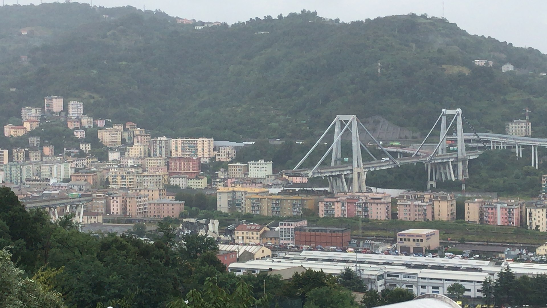
Ponte Morandi (Polcevera Viaduct) — Genoa, Italy

Ponte Morandi, Genoa, after 14 August 2018. Pylon 9 and 210 m of deck fell together — the stay, the pylon and the deck were one indivisible load path.

Photo: Wikimedia Commons (CC BY-SA)

Timeline

  1. 11:36

    Southernmost stay of pylon 9 fractures; 210 m of deck plus the pylon collapse into the Polcevera valley.

Engineering root cause

Corrosion of the internal steel strands beneath the concrete stay encasement, undetected because visual inspection could not see through the encasement. Non-redundant single-stay geometry.

Forensic findings

  • Morandi's signature detail encased the stay strands in prestressed concrete. The concrete was intended as corrosion protection; instead it hid section loss from every form of visual inspection.
  • Post-collapse examination of the recovered south stay of pylon 9 showed strand section loss locally exceeding 50%, concentrated at the upper anchorage where chlorides and water collected.
  • The structure had only two stays per side per pylon — the lowest possible redundancy for a cable-stayed form. Multi-stay harp or fan systems distribute loss of one cable.
  • Traffic loads had grown far beyond the 1967 design assumptions, and a 1990s retrofit had added stays to pylon 11 but not to pylon 9.

What it changed in the code

Reinforced European Bridge Inspection Directive; drove adoption of ultrasonic/magnetostrictive strand condition assessment. In the US, informs AASHTO Manual for Bridge Evaluation on element-level condition for encased tendons.

What you do differently today

  • Encased or grouted tendons require non-visual NDE: magnetic flux leakage, ultrasonic guided waves, or impact-echo/vacuum grout testing per PTI DC45.1.
  • Design cable systems so that loss of any one cable is a checkable limit state (fib and PTI both give the 1.1 DL + 0.75 LL sudden-loss check).
  • Provide replaceable, inspectable, individually greased-and-sheathed strands with load-cell monitoring at anchorages.
  • Instrument critical stays: acoustic emission monitoring detects individual wire breaks long before global capacity is threatened.

FIU Pedestrian Bridge

15 March 2018 · Miami, FL

Post-tensioned concrete truss (accelerated bridge construction)

6 fatalities
Chapter 18
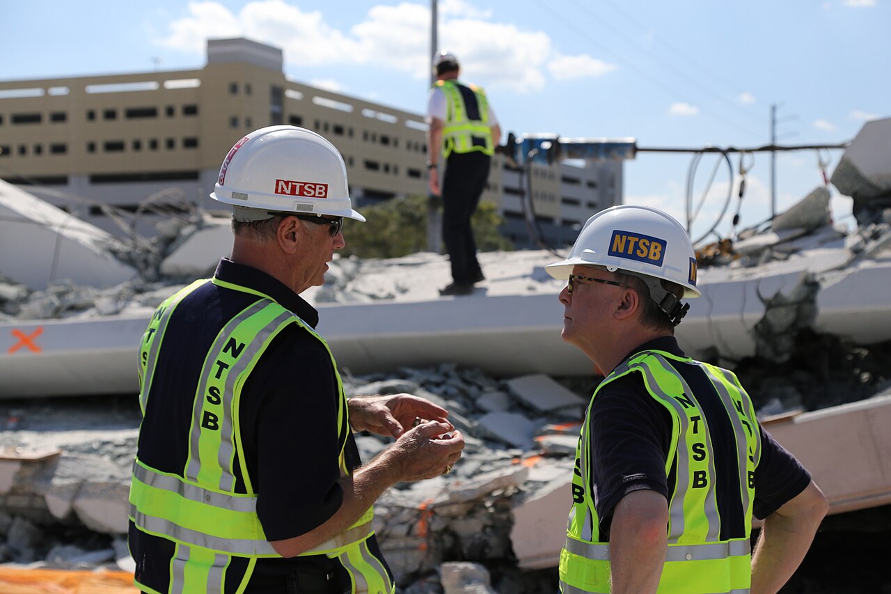
FIU Pedestrian Bridge — Miami, FL

The FIU–Sweetwater UniversityCity pedestrian bridge on SW 8th Street, 15 March 2018. The span had been in place five days and traffic was still flowing beneath it.

Photo: Wikimedia Commons (public domain)

Timeline

  1. 10 Mar 2018

    Span placed by SPMT onto piers over 8th Street. Traffic reopened underneath.

  2. 13 Mar

    Cracking observed at Node 11/12 diagonal-to-deck joint; interpreted as non-structural.

  3. 15 Mar 13:47

    PT bar retensioning underway on Member 11 while traffic flows below. Node 11/12 fails in shear; span collapses. 6 deaths.

Engineering root cause

Design underestimated cold-joint interface shear at Node 11/12 by ~50%; independent peer review missed it; retensioning under live traffic violated ABC risk protocols.

Forensic findings

  • The nodal region joining diagonal Member 11 and the deck was a cold joint with intentionally roughened but under-reinforced interface. Interface shear demand exceeded the AASHTO capacity by roughly a factor of two.
  • The design ignored the loss of confinement when the temporary erection blister at Node 11/12 was removed after the span was set.
  • Cracks up to 40 times the width considered acceptable were photographed on 13 March and circulated by email; the design engineer judged them non-structural over the phone.
  • The final act — retensioning the Member 11 PT bars to close the cracks — increased the horizontal thrust at the very joint that was already failing, and it was done above open traffic.

What it changed in the code

FHWA ABC Manual updated to require traffic closure during any PT operation on unfinished structures; AASHTO Guide Specifications for adopted mandatory independent design review at 30/60/90/100% for signature-structure ABC projects.

What you do differently today

  • Compute interface shear at every construction joint: V_ni = c·A_cv + μ(A_vf·f_y + P_c), with limits per §5.7.4.3.
  • Model every construction stage, including the moment when temporary supports or blisters are removed. The governing case is usually not the final one.
  • Any observed crack on a partially completed structure is structural until an engineer proves otherwise, in writing, with a calculation.
  • Close traffic under a structure during any post-tensioning, jacking or load-transfer operation — now explicit in the FHWA ABC Manual and AASHTO ABC Guide Specifications.

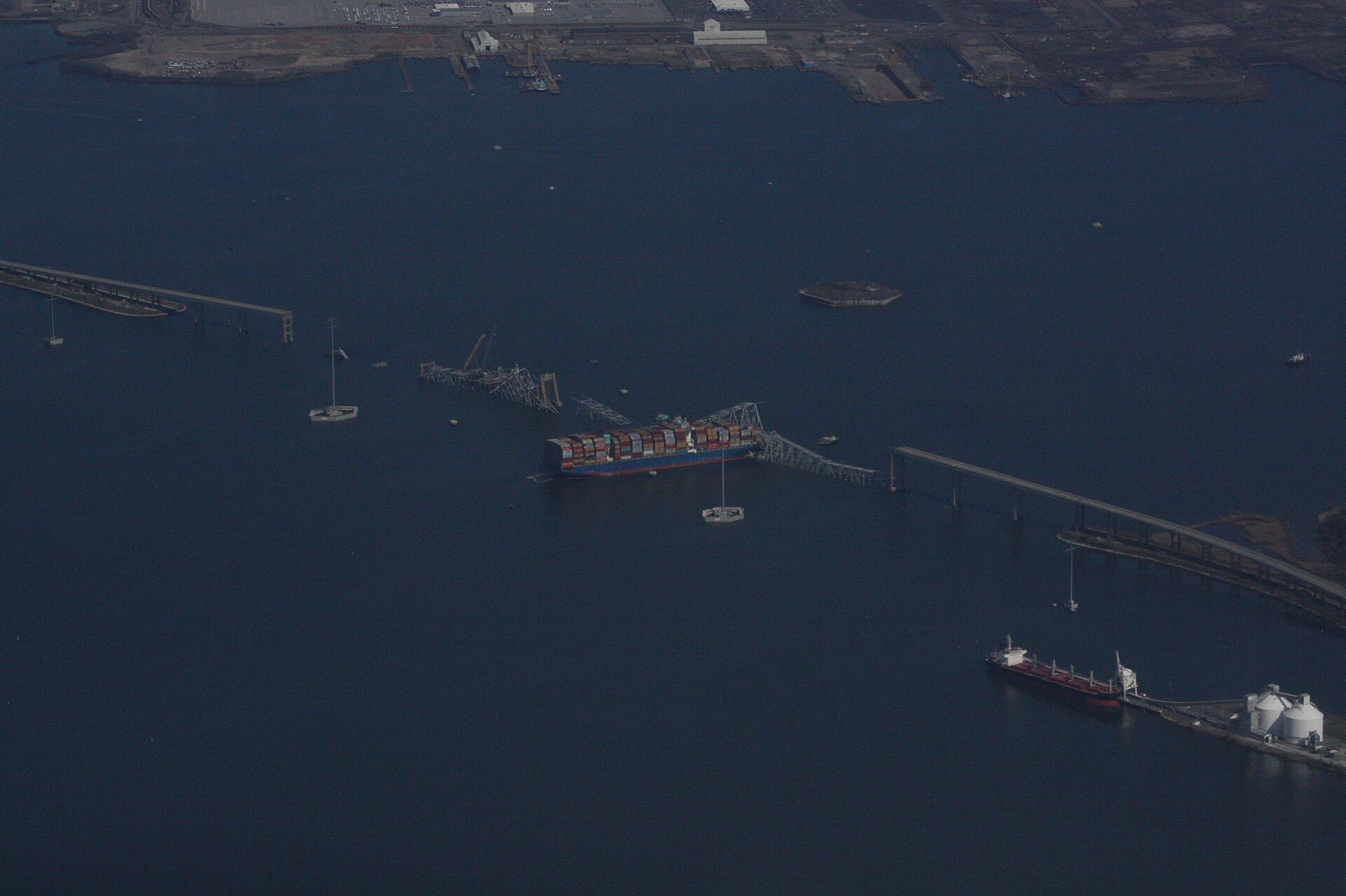
Francis Scott Key Bridge

26 March 2024 · Baltimore, MD — Patapsco River

Continuous steel through-truss with cantilever main span (1977, non-redundant)

6 fatalities
Chapter 16
Francis Scott Key Bridge — Baltimore, MD — Patapsco River

The Francis Scott Key Bridge across the Fort McHenry channel, March 2024. A single unprotected pier stood between a 116,000-DWT container ship and the whole main span.

Photo: U.S. Army Corps of Engineers / Wikimedia Commons (public domain)

Timeline

  1. 01:24

    Motor vessel Dali loses electrical power inside the Fort McHenry channel.

  2. 01:27

    Bow strikes the south main-span pier at ~8 knots; pier destroyed instantly.

  3. 01:29

    Entire truss main span collapses into the shipping channel. 6 construction workers killed.

Engineering root cause

1970s-era vessel-collision design envelope (WSDOT-style empirical loads, no probabilistic analysis) did not contemplate a modern 100,000-ton neopanamax container ship. No structural pier protection.

Forensic findings

  • The Dali is ~300 m long, 116,000 DWT, and struck at roughly 8 knots. The equivalent static impact force under is on the order of 10⁵ kips.
  • The bridge was designed in 1972–1977, before any vessel-collision provision existed in AASHTO. Design-era ships on the Patapsco were a fraction of today's displacement.
  • The main span was a continuous through-truss with cantilever arms: the pier that was struck supported the cantilever, so its loss unzipped the whole 1,200 ft main unit in about 20 seconds.
  • Pier protection consisted of small timber-and-concrete fenders sized for a far smaller design vessel; there were no dolphins or protective islands.

What it changed in the code

Post-collapse, FHWA and USACE issued advisories requiring re-evaluation of every fracture-critical or non-redundant bridge over deep-draft channels using AASHTO probability-of-collapse analysis with current fleet data.

What you do differently today

  • Run the §3.14 AF computation with current AIS fleet data, not the fleet from the year the bridge opened — vessel DWT has roughly quadrupled since 1977 on many US channels.
  • For an existing non-redundant bridge, protection is usually cheaper and faster than strengthening: dolphins, artificial islands and pile-supported fenders absorb energy before it reaches the pier.
  • Evaluate progressive-collapse behaviour: ask what happens if any one substructure unit is removed, and design or protect so the answer is not 'everything'.
  • FHWA's 2024 advisory asks every owner of a bridge over a deep-draft channel to complete a vulnerability assessment — this is now active professional work, not history.

Bridge Engineering and Design Using AASHTO LRFD

Graduate interactive textbook for civil engineering students. Aligned to AASHTO LRFD Bridge Design Specifications, 10th Edition (2024).

Regional focus

Maryland & Mid-Atlantic — MDOT SHA, VDOT, PennDOT, FHWA.

Educational notice

This educational application supplements, but does not replace, the official AASHTO LRFD Bridge Design Specifications, applicable state DOT manuals, project specifications, and professional engineering judgment.

© 2026 Dr. Steve Efe, Ph.D. All Rights Reserved.

Developed for engineering education. Unauthorized reproduction, distribution, or commercial use is prohibited.

v1.0 · Reference edition · Aligned to AASHTO LRFD, 10th Edition (2024)