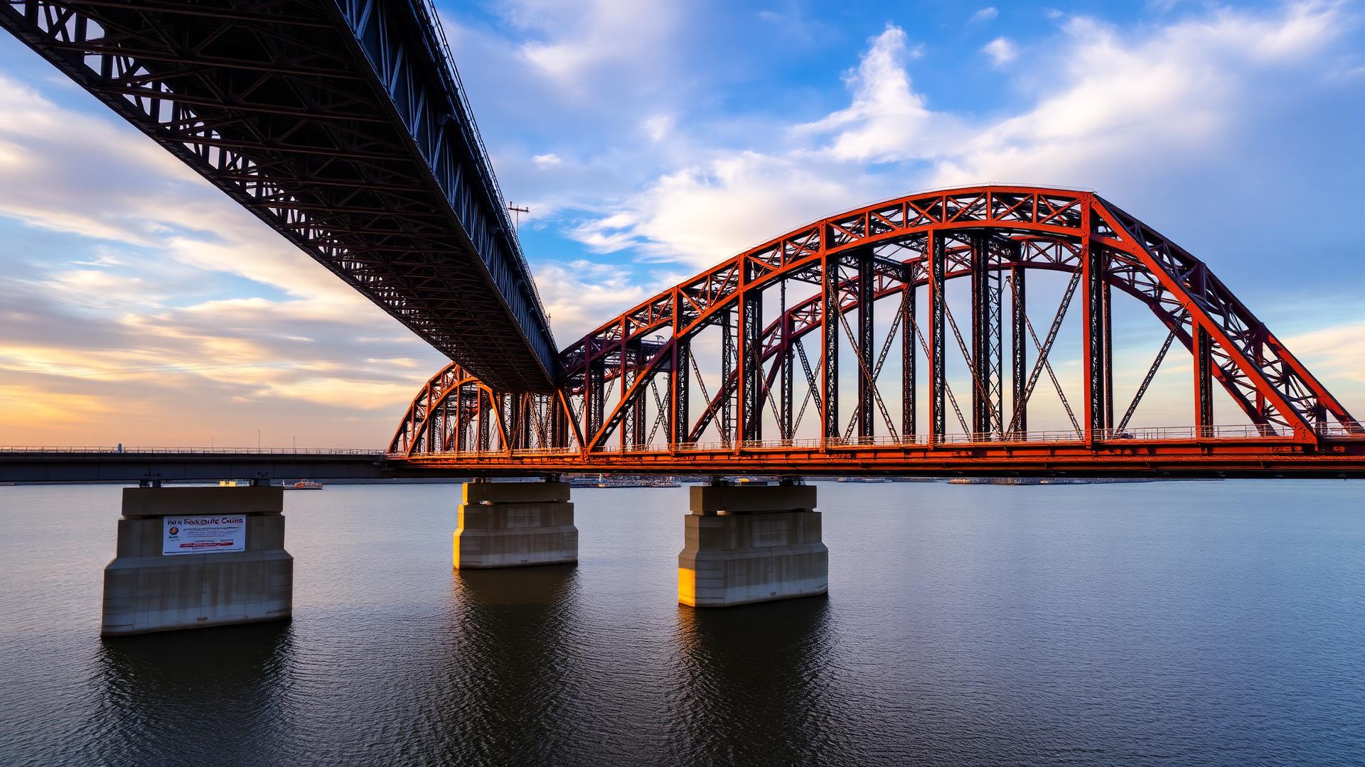
Engineering story
From Loma Prieta to capacity design
When the 1989 Loma Prieta earthquake collapsed the Cypress Viaduct and a section of the Bay Bridge — and when Northridge (1994) and Kobe (1995) followed — the profession stopped trying to make bridges elastic under strong ground motion and started making them ductile. Modern AASHTO seismic design accepts that a pier column will yield and rotate at a plastic hinge; the engineer's job is to choose where that hinge forms, detail it for rotation without loss of strength, and capacity-protect everything else — the bent cap, the connections, the foundation — so failure cannot migrate to a brittle element.
Chapter objectives
What you will be able to do
Learning objectives
By the end of this chapter you will be able to:
- 1Look up mapped short-period (S_S) and 1-s (S_1) accelerations and build the design response spectrum per AASHTO §3.4.
- 2Classify a bridge into Seismic Design Category A–D and pick the required analysis and detailing.
- 3Compute the fundamental period of a single-mode SDOF pier and read the elastic base shear from the spectrum.
- 4Apply the response modification factor R to obtain design forces and displacements (§3.10).
- 5Detail a column plastic hinge for confinement, longitudinal splices, and shear (AASHTO §5.10.11).
- 6Apply capacity design so that overstrength column moments protect the cap, joints, and foundation.
- 7Deliver two worked examples (spectrum-based base shear + confinement schedule) and a full-bridge seismic design challenge.
15.1 — Seismic hazard
Mapped ground motion and the design earthquake
AASHTO uses a 7 % probability of exceedance in 75 years design event (~1000-yr return period). USGS maps give the two ground motion parameters that anchor the design spectrum:
- — mapped short-period (0.2 s) spectral acceleration on Site Class B rock.
- — mapped 1.0-s spectral acceleration on Site Class B rock.
- — mapped peak ground acceleration.
Site coefficients Fpga, Fa, Fv (function of Site Class A–F per §3.10.3) scale the mapped values:
15.2 — Design response spectrum
The three-region curve
The AASHTO design acceleration spectrum has three regions built from SDS, SD1, and AS:
- 0.2 · T_S
- S_{D1}/S_{DS}
- long-period transition (from USGS map)
Seismic Design Categories (§3.10.6)
15.3 — Single-mode analysis
SDOF idealisation of a pier bent
For regular bridges (SDC B / C), a single-mode analysis is enough. The superstructure mass sits atop the pier acting as a lateral spring:
- tributary superstructure mass = W/g [kip·s²/ft]
- lateral stiffness of pier [kip/ft]
- effective moment of inertia (0.5–0.7 I_g cracked)
- clear column height [ft]
The elastic base shear from the spectrum is:
15.4 — Response modification
Ductility reduces elastic demand
AASHTO permits reducing elastic shear by a response modification factor R that reflects the ductility of the substructure element:
- R = 5 for multi-column bents (well-detailed).
- R = 3 for single-column piers.
- R = 1.5 for connections between substructure and superstructure — connections are not allowed to yield.
15.5 — Plastic hinges in columns
Where ductility is delivered
- distance to inflection point [in.]
- expected yield strength of longitudinal steel [ksi]
- longitudinal bar diameter [in.]
Plastic rotation capacity:
15.6 — Transverse confinement
Spiral / hoop reinforcement in the hinge zone
Minimum volumetric spiral ratio:
- vol. spiral steel / vol. concrete core
- gross and core section areas [in²]
- spiral yield stress [ksi]
Maximum spiral pitch s ≤ min(6·dbl, 6 in., D/4) inside the hinge zone.
15.7 — Capacity design
Overstrength column protects everything else
The plastic hinge is the fuse. To prevent brittle failure elsewhere, every other component is designed for the column overstrength moment:
The corresponding column shear is for a double-fixed column; the joint, cap, and foundation are designed for at least Vo.
15.8 — Seismic isolation
Lengthening the period at the interface
For high-seismic sites or retrofits, seismic isolators (lead-rubber, friction pendulum) placed between deck and substructure push the fundamental period out to 2–3 s, moving the structure into the descending 1/T branch of the spectrum and dissipating energy in a stable bilinear loop.
15.9 — Worked example 1
Design base shear on a two-column bent
Problem statement
A 60-ft-span highway bridge in California carries W = 900 kip of superstructure tributary weight onto a multi-column bent. Compute the design seismic base shear per column.
Given
- Mapped valuesSS = 1.4 g, S1 = 0.55 g, PGA = 0.55 g
- Site ClassD (Fa = 1.0, Fv = 1.5, Fpga = 1.0)
- PierH = 22 ft; two 4-ft-Ø columns, f′c = 4 ksi
- Effective inertiaIe = 0.5 Ig
- R-factorR = 5 (multi-column bent)
Required
Build the design spectrum, compute pier period T, elastic base shear V_e, and design shear V per column.
Step 1 — Design spectral accelerations (Eq. 15.1).
Formula
Substitute
Result
Formula
Substitute
Result
Step 2 — Pier stiffness and period. Two 4-ft columns act in parallel; Ig = π(4)⁴/64 = 12.57 ft⁴; Ie = 6.28 ft⁴. Ec = 3,600 ksi = 519,000 ksf.
Formula
Substitute
Result
Formula
Substitute
Result
Step 3 — Spectral acceleration. T > TS, use 1/T branch:
Formula
Substitute
Result
Wait: 0.825/0.9 = 0.917 g. That is above SDS = 1.40 g? No, 0.917 < 1.40, still on the descending branch (correct).
Step 4 — Elastic and design base shear.
Formula
Substitute
Result
Formula
Substitute
Result
Per column (two columns): V = 82.5 kip. Column moment at base for double-fixed action: M = V·H/2 = 82.5 × 11 = 908 kip-ft. Compare to plastic moment capacity Mp from the P-M interaction of the column section.
Final section detailing (from computed A_s)
Two-column bent — seismic demand (SDC D)
| Location | A_s required | Bars provided | Spacing / detail |
|---|---|---|---|
| Design spectrum | AASHTO Eq. 15.2, Site D | S_DS = 1.40 g, S_D1 = 0.825 g, T_S = 0.59 s | checked against USGS 2023 maps |
| Pier period T | Eq. 15.3 with cracked I_e | 0.87 s (descending branch) | re-check after column resizing |
| Elastic base shear | Eq. 15.4 | V_e = 825 kip / bent | govern in longitudinal dir. |
| R-factor | multi-column bent, ductile | R = 5 | R = 1.5 at connections |
| Design column shear | V_design = V_e/R | 165 kip / bent = 82.5 kip / column | detail M_o for capacity |
15.10 — Worked example 2
Spiral confinement in the plastic-hinge zone
Problem statement
For the 4-ft-Ø columns of the previous example, detail the transverse spiral in the plastic-hinge zone. Longitudinal reinforcement: 20 – #10 bars, f_y = 60 ksi, f_yh = 60 ksi, f′_c = 4 ksi. Clear cover 2.5 in.
Given
- D (gross diameter)48 in.
- D_core (to c.l. of spiral)48 − 2(2.5) − 0.5 = 43 in.
- A_gπ/4(48)² = 1,810 in²
- A_cπ/4(43)² = 1,452 in²
- Longitudinal bar diameter d_bl#10 → 1.27 in.
Required
Compute required spiral ratio and pitch for #4 spiral; specify the plastic-hinge length L_p and detail the transition to the regular zone.
Step 1 — Governing spiral ratio (Eq. 15.8).
Formula
Substitute
Result
Formula
Substitute
Result
Governing: ρs = 0.0080 (larger).
Step 2 — Spiral pitch for #4 (Asp = 0.20 in²).
Formula
Substitute
Result
Round down to 2 in. pitch would be conservative — but check upper bound: min(6·dbl, 6 in., D/4) = min(7.6, 6, 12) = 6 in. So 3 in. pitch satisfies ρs only if computed ratio ≥ required.
Formula
Substitute
Result
Use #4 spiral @ 2.25 in. pitch → ρs = 0.80/(43·2.25) = 0.0083 > 0.0080 ✓.
Step 3 — Plastic-hinge length (Eq. 15.6), H = 22 ft = 264 in.
Formula
Substitute
Result
Step 4 — Provide dense spiral over 2·L_p = 6 ft at each column end. Transition to regular pitch (#4 @ 4 in., ρs = 0.0047 ≥ min §5.10.6 requirement) above the hinge.
Final section detailing (from computed A_s)
Column confinement — plastic-hinge zone
| Location | A_s required | Bars provided | Spacing / detail |
|---|---|---|---|
| Longitudinal steel | ρ_l ≥ 0.008, ≤ 0.04 | 20 – #10 bars, ρ_l = 0.014 | clear cover 2.5 in. |
| Hinge spiral | ρ_s ≥ 0.0080 | #4 @ 2.25 in. pitch, ρ_s = 0.0083 | over 2·L_p = 6 ft from base |
| Above hinge | ρ_s ≥ 0.0045 | #4 @ 4 in. pitch, ρ_s = 0.0047 | full remaining column height |
| Splices | no lap splices in hinge zone | mechanical couplers only in L_p | staggered 4 ft |
| Cap-column joint | designed for M_o = 1.2 M_p | additional #6 stirrups + headed bars | AASHTO §5.10.11.4.4 |
15.11 — Guided practice
R-factor sensitivity check
Repeat Example 1 with a single-column pier (R = 3). Everything else the same. What is the design column shear? What does this tell you about substructure selection in high-seismic zones?
Expected result
15.12 — Mini design challenge
Four-span highway crossing in SDC D
Deliver:
- Design response spectrum from mapped values (SS = 1.5 g, S1 = 0.60 g, Site D). Classify SDC.
- Single-mode analysis in longitudinal and transverse directions; period, spectral acceleration, and elastic base shear.
- R-factor reduction, column P-M interaction check at each bent.
- Plastic-hinge length and spiral confinement schedule (both hinge and regular zones).
- Capacity-design demands (Mo, Vo) on bent cap, cap-column joint, and foundation.
- Isolation-bearing sizing at abutments and check of resulting deck displacements/support length.
- Foundation schedule and a one-page seismic design memo.
Submit your design challenge
Upload your seismic design memo (PDF)
You must be signed in to upload a submission.
Sign in →15.13 — Chapter summary
What you leave with
- USGS-mapped ground motion → design spectrum (Eq. 15.2) → SDC assignment.
- SDOF period from cracked pier stiffness (Eq. 15.3) and elastic base shear V_e = S_a W.
- Response modification factor R reduces elastic demand to design forces (multi-column R = 5, single R = 3, connections R = 1.5).
- Plastic hinges at column ends — length L_p (Eq. 15.6), rotation θ_p, and spiral confinement ρ_s (Eq. 15.8).
- Capacity design: cap, joints, and foundation sized for column overstrength moment M_o = 1.2–1.4 M_p.
- Base isolation for retrofit or high-seismic new construction — lengthen T, add damping.
Section 2
Fully Worked Examples
Complete AASHTO LRFD solutions with knowns, assumptions, step calculations, verification, and design commentary. Difficulty rises from basic to consulting-grade.
Worked Example 1
Problem
Step-by-Step
High-seismic (SDC D)
Design Verification
Any site with S_D1 > 0.50 is SDC D; expect ductile detailing and capacity design.
Discussion
Hazard is a site property, not a design choice. Everything downstream flows from these three numbers.
Worked Example 2
Problem
Step-by-Step
A_s
S_DS
S_D1
SDS=1.80, SD1=1.05
Design Verification
Long-period ordinate at T = 1.0 s is exactly S_D1 = 1.05 g — makes intuitive sense.
Discussion
Site Class D is a common default; if a real Vs30 shear-wave survey is done, F_a and F_v drop by 10–25%.
Worked Example 3
Problem
Step-by-Step
Formula
Result
Design Verification
Order of magnitude: pier base shear ≈ 1.8× deck weight — typical for SDC D short-period bridges.
Discussion
Long-period bridges (T > 1 s) fall on the descending spectrum branch and attract much less force; period-shifting via isolation exploits this.
Worked Example 4
Problem
Step-by-Step
Design Verification
ρ_l = 2% is within Guide Spec allowable 1–4%.
Discussion
SDC D forces capacity-based design of shear, hoops, joint. Longitudinal ρ is only step 1.
Worked Example 5
Problem
Step-by-Step
Ductility-dependent. Assume μ_D = 4 → α′ = 0. V_c = 0 in the plastic hinge zone.
Design Verification
Outside the plastic hinge, spacing may relax to 6 in.
Discussion
Modern SDC D detailing produces hoop-dominated columns — the goal is confinement, not just shear strength.
Worked Example 6
Problem
Step-by-Step
Design Verification
Isolator displacement → ~ 8 in. Design isolator with 12-in displacement capacity for safety.
Discussion
Isolation is the single biggest lever in seismic design — but adds first cost, expansion joint complications, and inspection.
Worked Example 7
Problem
Step-by-Step
Design Verification
Guide Spec §4.7: check construction stages when duration > 1 yr; reduce design event to 500-yr return.
Discussion
Long-duration construction on high-seismic sites must be staged with braces or temporary shear connections.
Worked Example 8
Problem
Step-by-Step
(1) Steel shell jacket 3/8 in; (2) FRP wrap 4 layers of CFRP; (3) Concrete jacket +6 in with #6 spiral.
Formula
Result
Design Verification
CFRP retrofit validated by extensive PEER database of column tests (Priestley/Seible 1996).
Discussion
Cost per column: FRP $8k, steel jacket $18k, concrete jacket $25k. FRP dominates 1990s→ retrofit programs (Caltrans Phase II).
Worked Example 9
Problem
Step-by-Step
Design Verification
Reproduces PEER back-analysis of Priestley et al. Direct driver of Guide Spec §8.13 joint shear provisions in 1995.
Discussion
Joint shear is invisible in code books before 1990; every pre-1990 outrigger bent in high-seismic zone should be re-checked.
Worked Example 10
Problem
Step-by-Step
Multi-mode spectral; T_1,long = 1.1 s, T_1,trans = 0.85 s.
Design Verification
Push-over analysis shows plastic hinge ductility μ_D = 4.2 < μ_D,cap = 6 per Guide Spec.
Discussion
Modern SDC D bridges are 20–35% more expensive than SDC A equivalents; isolation typically pays back through smaller foundations.
Section 4
Independent Practice
Every problem randomizes its inputs. Work each step, submit for immediate feedback, request new values to practice again.
Practice 1
Practice 2
Practice 3
Practice 4
Practice 5
Practice 6
Practice 7
Practice 8
Practice 9
Practice 10
Practice 11
Practice 12
Section 5
Design Challenges
Multi-day projects mirroring real consulting scope. Submit a report package for review.
Project 1
Scope
Green-field bridge on CA SR-58, three 140-ft continuous concrete box spans, , . Two single-column bents, drilled-shaft foundations. Deliver a full seismic design report to Caltrans SDC-2019 standards.
Deliverables
- Modal response spectrum analysis (min 3 modes each direction) with tabulated periods and mass participation.
- Column longitudinal & transverse reinforcement design incl. plastic-hinge detailing.
- Capacity-protected design of joints, bent cap, and foundations to M_po.
- Displacement demand vs capacity check (Δ_c/Δ_d ≥ 1.5).
- Foundation drilled-shaft layout and axial-lateral capacity check.
- Bearing/isolator selection with movement demands.
- Bid quantities: concrete CY, rebar T, shaft feet.
Constraints
- SDC D per AASHTO Guide Spec.
- Ductility μ_D ≤ 6.
- Foundation shaft group efficiency ≥ 0.85.
- Column ρ_l between 1% and 4%.
Grading Rubric
- Correct seismic hazard characterization10%
- Modal analysis quality15%
- Column design & capacity-based sizing25%
- Capacity-protected member consistency20%
- Foundation design15%
- Quantities & deliverables completeness15%
Submit your design challenge
Design a 3-span RC bridge for SDC D from scratch
You must be signed in to upload a submission.
Sign in →Project 2
Scope
Existing 1970 double-deck RC viaduct on I-880 approach: 15 continuous spans, non-ductile RC columns, outrigger bents, no joint shear reinforcement. Owner has $18M budget. Recommend and design a retrofit that brings the structure to SDC D life-safety performance.
Deliverables
- Vulnerability screening: identify all deficiencies vs current Guide Spec.
- Retrofit alternatives matrix (column FRP, steel jacket, concrete overlay, isolation, replacement).
- Preferred alternative full design: column wrap thickness, joint retrofit, cap beam post-tensioning if needed.
- Foundation adequacy check post-retrofit.
- Construction staging plan preserving 1 lane in each direction.
- Bid quantities and cost estimate versus budget.
Constraints
- Budget cap $18M.
- One lane must remain open each direction during construction.
- Retrofit must not reduce vertical clearance below 15 ft.
- Design must be re-inspectable per NBIS.
Grading Rubric
- Vulnerability screening thoroughness20%
- Alternatives evaluation & selection logic20%
- Design correctness of preferred retrofit25%
- Construction staging feasibility15%
- Cost-benefit vs budget20%
Submit your design challenge
Seismic retrofit of a 1970 non-ductile viaduct
You must be signed in to upload a submission.
Sign in →