SE

This educational application supplements, but does not replace, the official AASHTO LRFD Bridge Design Specifications, applicable state DOT manuals, project specifications, and professional engineering judgment.

Chapter 08

Steel I-Girder and Plate-Girder Bridges

Rolled and welded plate composite steel girders. Section classification, plastic and yield-moment resistance, LTB, shear with tension-field action, shear stud design, and Category-C fatigue. Includes a full 2×140-ft continuous composite plate-girder worked example and a curved-girder mini design challenge.

Estimated Time

12 Hours

Difficulty

Advanced

AASHTO Refs

7 sections

Focus Area

Steel Girders

Bookmark

Chapter

Engineering story

Why steel dominates the medium-span crossing

Between 120 and 300 feet — the range that covers most highway grade separations, river crossings, and interchange ramps — the composite steel plate girder is the workhorse of North American bridge construction. It is light enough to ship and erect in single pieces, deep enough to control deflection over long spans, and tunable: the designer chooses each flange and web plate independently and varies them along the span so the section grows only where the moment demands it. A well-designed plate girder can weigh 30% less than a rolled shape of equivalent capacity, and that steel weight drives the substructure cost.

This chapter is the AASHTO §6.10 workflow for I-shaped steel girders acting compositely with a concrete deck. We classify the section (compact / non-compact / slender), compute the plastic moment MpM_p, check lateral-torsional buckling for the non-composite construction stage, size web shear with or without tension-field action, design the shear-stud interface that makes the section composite, and check Category-C fatigue at every web-to-flange weld. Every calculation follows the Formula → Substitute → Result pattern.

Chapter objectives

What you will be able to do

Learning objectives

By the end of this chapter you will be able to:

  1. 1Choose between rolled W-shapes and welded plate girders based on span, depth, and economy.
  2. 2Compute short-term (n) and long-term (3n) composite section properties for the deck-plus-steel system.
  3. 3Classify a composite section as compact or non-compact per AASHTO §6.10.6 and §B6.
  4. 4Locate the plastic neutral axis and compute Mp using the seven AASHTO PNA cases.
  5. 5Check lateral-torsional buckling of the non-composite construction stage using Lp, Lr, and the Cb moment-gradient factor.
  6. 6Design the web for shear per §6.10.9: nominal shear Vn, panel aspect do/D, and tension-field contribution.
  7. 7Size shear-stud connectors at strength (§6.10.10.4) and fatigue (§6.10.10.2) limit states.
  8. 8Detect and detail transverse and bearing stiffeners per §6.10.11.
  9. 9Check web-to-flange weld fatigue as Category C using the AASHTO nominal fatigue resistance ΔF(TH).
  10. 10Estimate live-load and dead-load deflections and meet the §2.5.2.6.2 optional deflection limits.

8.1 — Steel superstructure systems

Rolled shapes, plate girders, and box girders

AASHTO LRFD §6.10.1

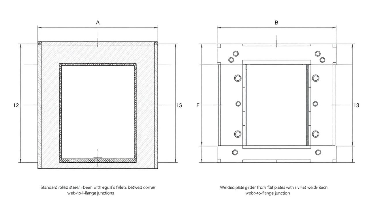
Three families cover most highway steel bridges. Rolled W-shapes (e.g. W40×324) come out of the mill with fixed proportions; they are the fastest and cheapest choice up to about 100 ft spans. Welded plate girders are fabricated from three plates (top flange, web, bottom flange) with continuous fillet welds; they cover 100–300 ft simple and continuous spans and allow flange transitions where the moment envelope requires. Steel box girders add a second web and a closed cell — they are torsionally stiff, ideal for curved alignments and long single-cell crossings.

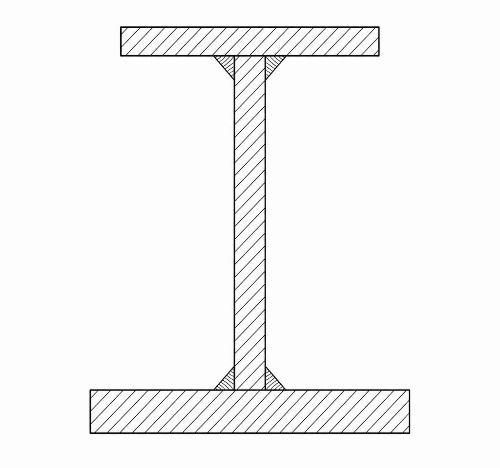
Comparison of a rolled W-shape and a welded plate girder cross section
Figure 8.1Rolled W-shape (left) has fixed flange/web proportions set by the mill; a welded plate girder (right) lets the designer pick each plate independently and vary them along the span.
AttributeRolled W-shapeWelded plate girderSteel box girder
Typical span range40 – 100 ft100 – 300 ft150 – 500 ft
Depth-to-span1/25 – 1/301/28 – 1/331/30 – 1/40
Fabrication costLowestMediumHighest
Curved alignmentsPoorFair (multiple straight chords)Excellent
Fracture-criticalNo (redundant multi-girder)No (redundant)Sometimes (single tub)

8.2 — Steels used in bridges

ASTM grades and toughness

AASHTO LRFD §6.4.1

AASHTO M270 is the umbrella specification for bridge structural steel. Four grades cover 99% of practice:

GradeFy (ksi)Fu (ksi)Notes
363658Rare in new work; retrofits.
505065Default for rolled shapes.
50W5070Weathering; no paint if detailed correctly.
HPS 70W7085High performance; ideal for negative-moment regions of continuous girders.

AASHTO §6.4.1 — Charpy V-notch toughness

Every primary steel component in a tension zone must meet a minimum CVN energy at the site's Zone 1/2/3 service temperature. Fracture-critical members require higher CVN values with tighter test frequency. Specify the zone and the fracture-critical flag on the shop drawings — do not leave it to the mill.

8.3 — Composite behavior

Making the deck work with the steel

AASHTO LRFD §6.10.1.1, §4.6.2.6

When shear studs anchor the deck to the top flange, the deck concrete carries compression in positive-moment regions and the neutral axis rises up into (or near the top of) the deck. That single geometric change roughly doubles the section modulus of the bare steel girder. AASHTO uses a modular ratio n=Es/Ecn = E_s / E_c to transform the deck into an equivalent steel area. For short-term live loads use nn; for long-term dead loads (creep) use 3n3n so the composite stiffness is reduced to reflect creep of the concrete.

Composite steel plate girder cross section with concrete deck and shear studs
Figure 8.2Composite section: the deck's effective width b_eff (§4.6.2.6) is transformed to steel using n for live load or 3n for sustained load, and the neutral axis of the composite section moves up toward the deck.
n  =  EsEc,Ec  =  33,000wc1.5fcn \;=\; \dfrac{E_s}{E_c}, \qquad E_c \;=\; 33{,}000 \, w_c^{1.5} \, \sqrt{f'_c}
EsE_s
Steel modulus of elasticity [ksi]
EcE_c
Concrete modulus of elasticity [ksi]
wcw_c
Concrete unit weight [kcf]
fcf'_c
Concrete compressive strength [ksi]

8.4 — Section classification

Compact, non-compact, slender

AASHTO LRFD §6.10.6.2, §B6

A compact section can develop and sustain the full plastic moment MpM_p before local or lateral instability. A non-compact section reaches only the yield moment MyM_y. A slender web buckles before yield and requires reduced-strength or hybrid design (§6.10.1.10). For composite sections in positive flexure the deck restrains the compression flange, so classification hinges on the web slenderness 2Dcp/tw2 D_{cp}/t_w:

2Dcptw    3.76EFyc    compact web\dfrac{2 \, D_{cp}}{t_w} \;\le\; 3.76 \, \sqrt{\dfrac{E}{F_{yc}}} \qquad \Rightarrow \;\; \text{compact web}
(6.10.6.2.2-1)
DcpD_{cp}
Depth of web in compression at the plastic moment [in]
twt_w
Web thickness [in]
FycF_{yc}
Compression-flange yield stress [ksi]

If the ratio exceeds this limit but is below 5.70E/Fyc5.70\sqrt{E/F_{yc}}, the web is non-compact; above 5.70E/Fyc5.70\sqrt{E/F_{yc}} it is slender.

8.5 — Flexural resistance

Plastic moment Mp — the seven PNA cases

AASHTO LRFD §D6.1, §6.10.7

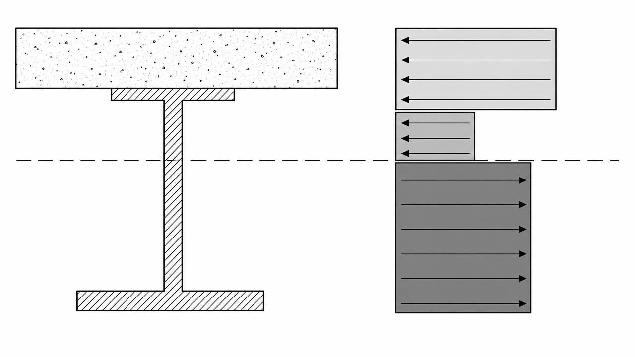
The plastic moment of a composite section is found by locating the plastic neutral axis (PNA) so that the compressive force above equals the tensile force below. AASHTO tabulates seven cases depending on whether the PNA lies in the slab, the top flange, or the web. In every case the deck carries a rectangular Whitney block of depth aa at 0.85fc0.85 f'_c, and each steel component acts at FyF_y throughout its depth.

Plastic stress distribution across a composite steel girder cross section
Figure 8.3Plastic stress distribution: concrete deck at 0.85 f'c above the PNA, steel at Fy in compression above and Fy in tension below. Summing internal forces to zero locates the PNA.
Mp  =  Cdeckd1  +  Ctfd2  +  Twd3  +  Tbfd4M_p \;=\; C_{deck} \, d_1 \;+\; C_{tf} \, d_2 \;+\; T_w \, d_3 \;+\; T_{bf} \, d_4
(6.10.7.1.2-2)
CdeckC_{deck}
Deck compression = 0.85 f'c b_eff a [kip]
Ctf,Tw,TbfC_{tf}, T_w, T_{bf}
Steel force resultants above/below PNA [kip]
d1d4d_1 \ldots d_4
Lever arms from each resultant to the PNA [in]

Schematic form — the exact expression depends on which PNA case controls; see AASHTO Table D6.1-1.

Ductility check §6.10.7.3

Even compact composite sections in positive flexure must satisfy Dp0.42DtD_p \le 0.42\, D_t, where DpD_p is the distance from the top of the deck to the PNA and DtD_t is the total composite depth. A deep PNA (high DpD_p) means the section is barely ductile and the plastic resistance must be discounted.

8.6 — Lateral-torsional buckling

The non-composite construction stage

AASHTO LRFD §6.10.8.2, §6.10.3.4

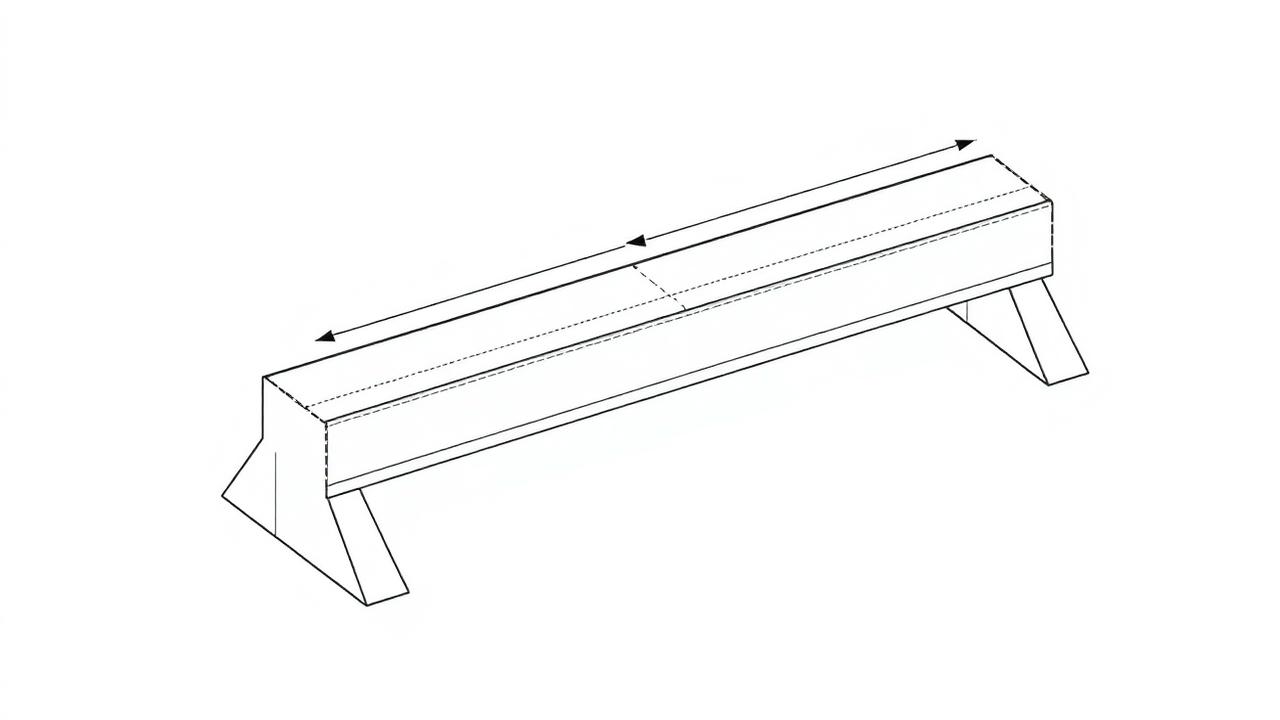
Before the deck cures the girder is a bare steel I-beam with the wet-concrete load on top. The compression flange is braced only by the cross-frames, so LTB can govern. AASHTO frames LTB with two length limits:

Lateral-torsional buckling of a steel I-beam between cross-frames
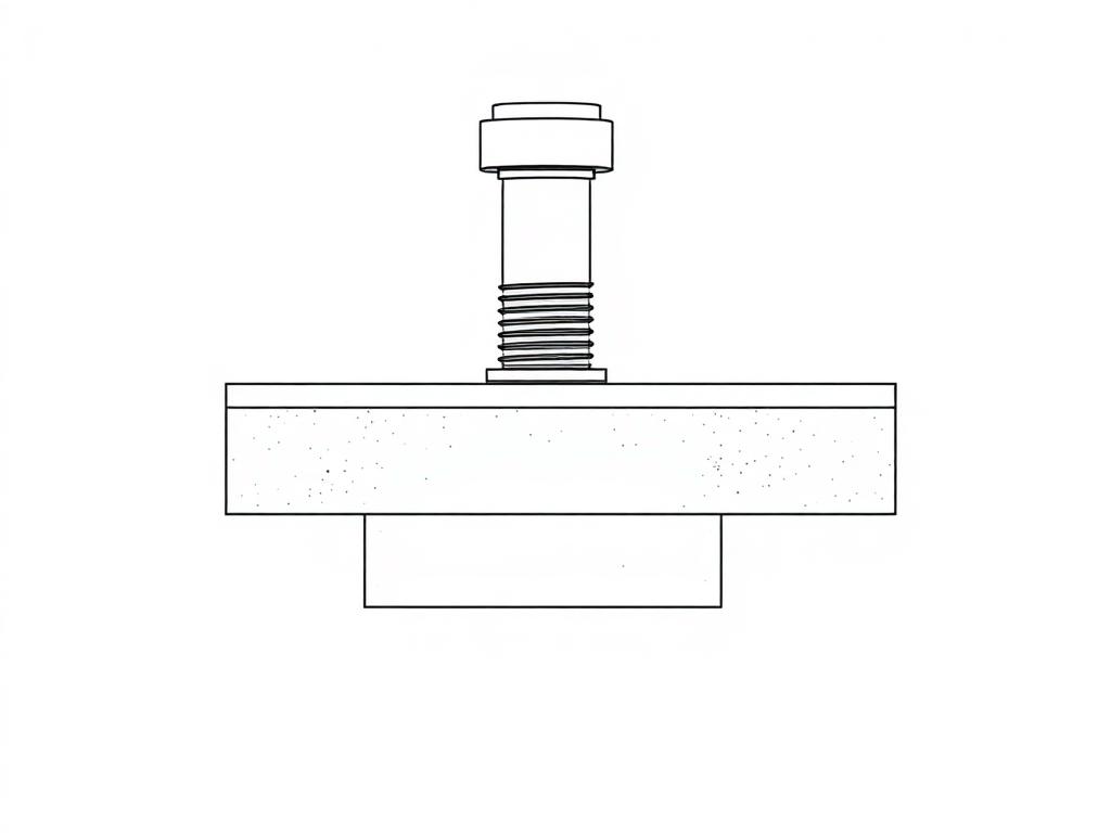
Figure 8.4LTB of the compression flange between cross-frames spaced Lb apart. Bracing at the tenth-points during deck placement is the cheapest way to keep Lb ≤ Lp so the plastic branch controls.
Lp  =  1.0rtEFycL_p \;=\; 1.0 \, r_t \, \sqrt{\dfrac{E}{F_{yc}}}
(6.10.8.2.3-4)
Lr  =  πrtEFyr,Fyr  =  0.7FycL_r \;=\; \pi \, r_t \, \sqrt{\dfrac{E}{F_{yr}}}, \qquad F_{yr} \;=\; 0.7 \, F_{yc}
(6.10.8.2.3-5)
  • If LbLpL_b \le L_pFnc=RbRhFycF_{nc} = R_b R_h F_{yc} (plastic branch).
  • If Lp<LbLrL_p < L_b \le L_r → linear inelastic reduction.
  • If Lb>LrL_b > L_r → elastic LTB, Fcr=CbRbπ2E(Lb/rt)2F_{cr} = \dfrac{C_b R_b \pi^2 E}{(L_b/r_t)^2}.

8.7 — Web shear resistance

With and without tension-field action

AASHTO LRFD §6.10.9

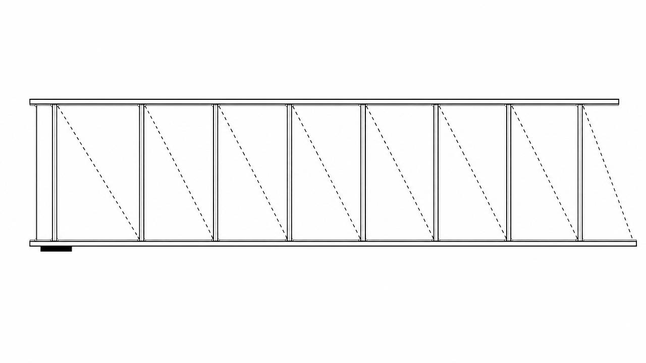
Shear in an I-girder is carried almost entirely by the web. Two mechanisms exist: pure elastic shear buckling (thin web, no stiffeners), and post-buckling tension-field action once the web is stiffened at spacing dod_o. AASHTO gives:

Steel web with transverse and bearing stiffeners and the tension-field pattern
Figure 8.5Transverse stiffeners at spacing do divide the web into panels that develop tension-field action after elastic buckling. A bearing stiffener over each support transfers the reaction into the web without local crippling.
Vn  =  Vp[C  +  0.87(1C)1+(do/D)2]V_n \;=\; V_p \left[\, C \;+\; \dfrac{0.87 \,(1 - C)}{\sqrt{1 + (d_o / D)^2}}\,\right]
(6.10.9.3.2-2)
Vp  =  0.58FywDtwV_p \;=\; 0.58 \, F_{yw} \, D \, t_w
(6.10.9.2-1)

The ratio CC is the elastic web-shear-buckling coefficient — a function of D/twD/t_w and do/Dd_o/D. If do3Dd_o \ge 3D the panel is “unstiffened” and only the elastic CVpC \, V_p term is used.

8.8 — Shear-stud connectors

Making composite action real

AASHTO LRFD §6.10.10

Composite action lives or dies with the shear studs. AASHTO requires two checks: fatigue (§6.10.10.2) — the studs handle the horizontal shear range from every truck cycle — and strength (§6.10.10.4) — the cumulative stud capacity between the point of zero moment and the point of maximum moment must equal or exceed the total horizontal thrust needed to develop MpM_p.

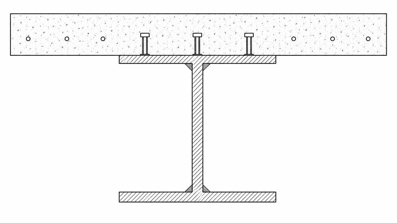
Welded shear stud connectors on the top flange embedded in the concrete deck
Figure 8.67/8-in diameter × 6-in tall welded shear studs are the industry standard. Center-to-center pitch p is set by fatigue at the girder end and grows toward mid-span.
Qr  =  ϕscQn,Qn  =  0.5AscfcEc    AscFuQ_r \;=\; \phi_{sc} \, Q_n, \qquad Q_n \;=\; 0.5 \, A_{sc} \, \sqrt{f'_c \, E_c} \;\le\; A_{sc} \, F_u
(6.10.10.4.3-1)
p    nZrVsrp \;\le\; \dfrac{n \, Z_r}{V_{sr}}
(6.10.10.2-1)
ZrZ_r
AASHTO fatigue shear resistance per stud [kip]
VsrV_{sr}
Horizontal shear range per unit length at section [kip/in]
nn
Number of studs per transverse row []

8.9 — Fatigue and fracture

Category C is not optional

AASHTO LRFD §6.6.1.2

Every weld detail is assigned a fatigue category A–E based on its geometry and residual-stress state. The web-to-flange fillet weld on a plate girder is Category C (or C′ where transverse stiffeners are welded to the tension flange). The stress range under the AASHTO Fatigue-I truck (γ=1.5\gamma = 1.5) must not exceed the nominal fatigue resistance ΔFn\Delta F_n.

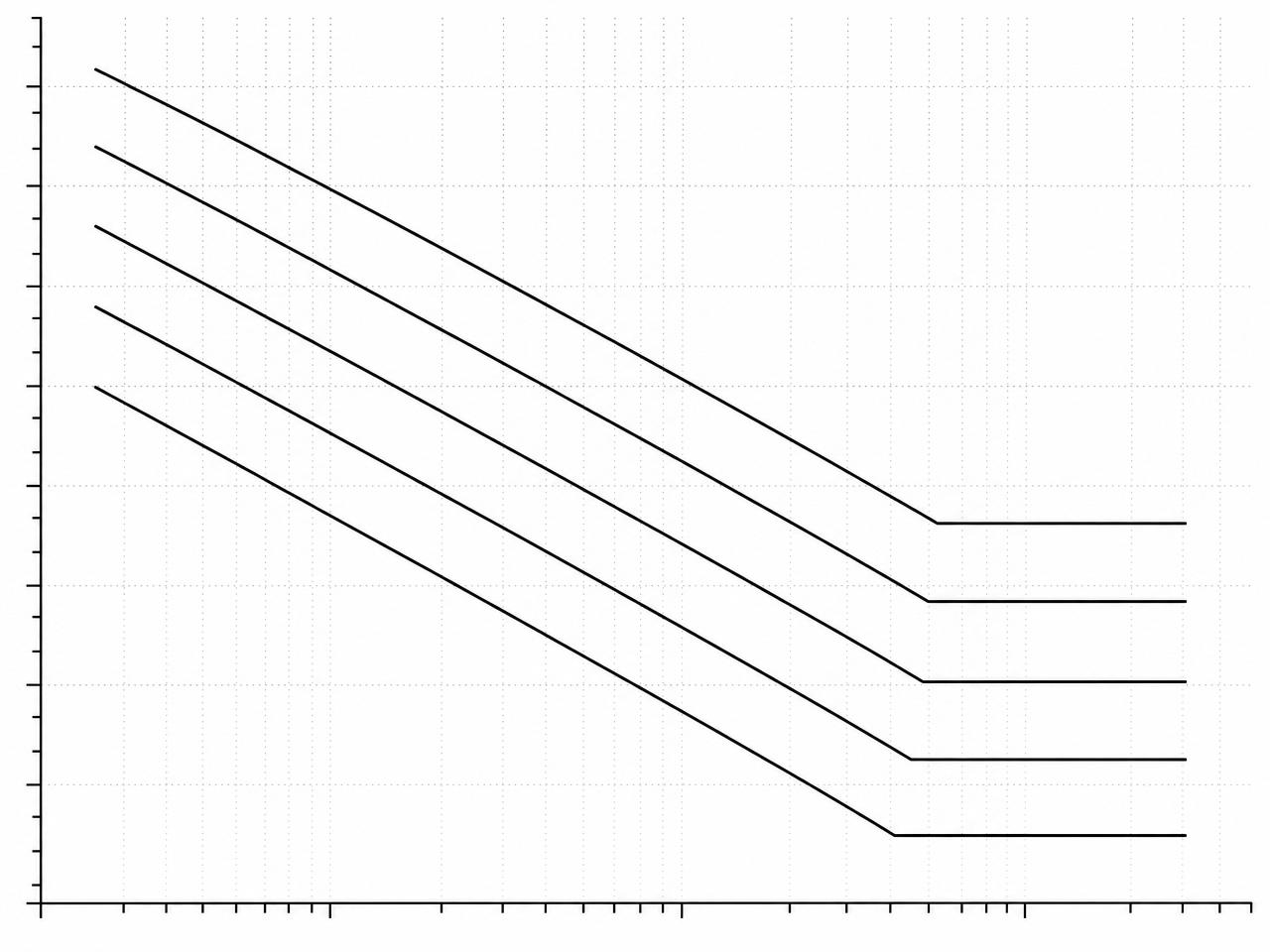
AASHTO fatigue S-N curves for detail categories A through E
Figure 8.7AASHTO S-N curves. Each detail category has a constant-amplitude fatigue threshold ΔF(TH) below which infinite life is assumed.
ΔFn  =  (AN)1/3    12ΔFTH\Delta F_n \;=\; \left(\dfrac{A}{N}\right)^{1/3} \;\ge\; \dfrac{1}{2}\, \Delta F_{TH}
(6.6.1.2.5-1)
CategoryA (× 10⁸)ΔF(TH) (ksi)Typical detail
A25024Base metal, rolled surface
B12016Longitudinal groove weld
C4410Web-to-flange fillet, transverse stiffener terminations
D227Fillet-welded cover plate ends
E114.5Long attachments, cover plates > 4·flange width

8.10 — Worked example

Two-span continuous composite plate girder, 2 × 140 ft

AASHTO LRFD §6.10 full check
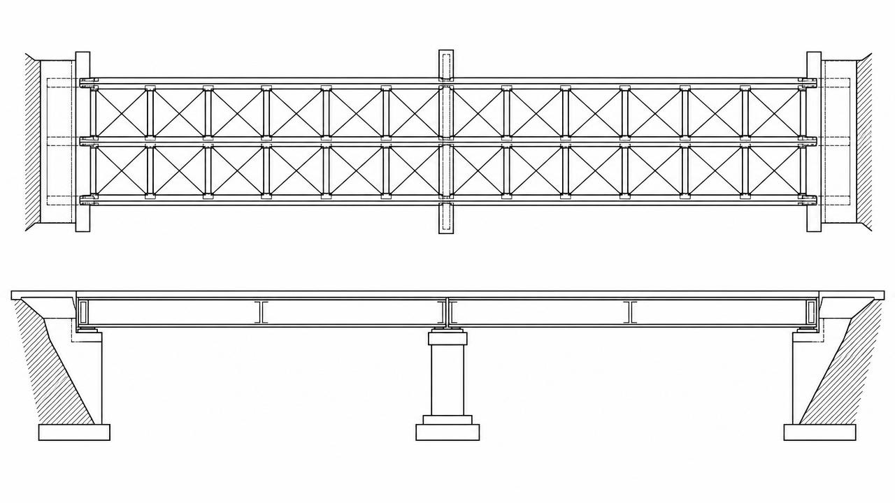
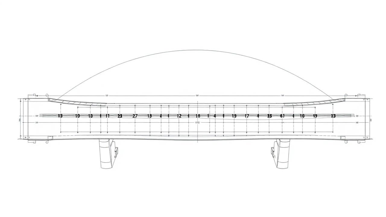
Plan and elevation of a two-span continuous composite steel plate girder bridge
Figure 8.8Two-span continuous composite plate girder bridge: 2 × 140 ft, 44 ft roadway, 4 girders at 11 ft, 9-in deck. Design the positive-moment interior girder for Strength I.

Problem statement

Design the interior plate-girder positive-moment section at mid-span of the first span. Bridge has two equal continuous spans.

Given

  • Span layout2 × 140 ft continuous
  • Girder spacing S11.0 ft (4 girders, 44 ft roadway)
  • Deck thickness t_s9.0 in (0.5-in wearing surface deducted)
  • Steel gradeAASHTO M270 Grade 50W (Fy = 50 ksi)
  • fcf'_c4.0 ksi
  • Modular ratio n8 (short-term)
  • Cross-frame spacing L_b20 ft (construction stage)
  • Trial sectionTop fl 16×1.0, Web 66×0.5, Bot fl 20×1.5
  • Strength-I moment M_uM(DC1)=1,180 + M(DC2)=310 + M(LL+IM)=2,540 → Mu ≈ 6,470 kip-ft
  • Strength-I shear V_u≈ 620 kip at first interior support

Required

Check section classification, plastic moment, LTB during deck placement, web shear (with stiffeners), shear-stud pitch, and Category-C fatigue at mid-span.

Step 1

Section properties

Trial welded plate girder cross section with dimensioned top flange, web, and bottom flange
Figure 8.9Trial welded section: top flange 16×1.0, web 66×0.5, bottom flange 20×1.5. Total depth 68.5 in; span/depth ≈ 140·12/68.5 ≈ 24.5 — within AASHTO §2.5.2.6.3 for continuous composite.

Area of steel section

As  =  bfttft  +  Dtw  +  bbftbfA_s \;=\; b_{ft}\, t_{ft} \;+\; D\, t_w \;+\; b_{bf}\, t_{bf}

Substitute

As  =  16(1.0)+66(0.5)+20(1.5)  =  16+33+30A_s \;=\; 16(1.0) + 66(0.5) + 20(1.5) \;=\; 16 + 33 + 30

Result

As  =  79.0  in2A_s \;=\; 79.0 \;\text{in}^2

Effective flange width (AASHTO §4.6.2.6.1)

beff  =  min ⁣(S,    12ts+max(tw,bft/2),    L4)b_{eff} \;=\; \min\!\left(\, S,\;\; 12 t_s + \max(t_w, b_{ft}/2),\;\; \dfrac{L}{4}\,\right)

Substitute

beff  =  min ⁣(11(12),    12(9)+max(0.5,8),    140(12)4)=min(132,116,420)b_{eff} \;=\; \min\!\left(\, 11(12),\;\; 12(9) + \max(0.5, 8),\;\; \dfrac{140(12)}{4}\,\right) = \min(132,\, 116,\, 420)

Result

beff  =  116  inb_{eff} \;=\; 116 \;\text{in}

Short-term transformed deck area

Adeck,n  =  befftsnA_{deck,n} \;=\; \dfrac{b_{eff} \, t_s}{n}

Substitute

Adeck,n  =  116(9)8  =  1,0448A_{deck,n} \;=\; \dfrac{116 \,(9)}{8} \;=\; \dfrac{1{,}044}{8}

Result

Adeck,n  =  130.5  in2  (steel equivalent)A_{deck,n} \;=\; 130.5 \;\text{in}^2 \; (\text{steel equivalent})

Step 2

Section classification (§6.10.6.2.2)

Assume PNA falls in the web; check web slenderness using Dcp30  inD_{cp} \approx 30 \;\text{in} (from Step 3).

Formula

2Dcptw    3.76EFyc\dfrac{2 \, D_{cp}}{t_w} \;\le\; 3.76 \, \sqrt{\dfrac{E}{F_{yc}}}

Substitute

2(30)0.5  =  120vs.3.7629,00050  =  3.76580  =  90.6\dfrac{2 \,(30)}{0.5} \;=\; 120 \quad \text{vs.} \quad 3.76 \, \sqrt{\dfrac{29{,}000}{50}} \;=\; 3.76 \, \sqrt{580} \;=\; 90.6

Result

120  >  90.6        non-compact web — use §6.10.7.2 (yield moment approach)120 \;>\; 90.6 \;\;\Rightarrow\;\; \text{non-compact web — use §6.10.7.2 (yield moment approach)}

What can go wrong

The web is non-compact, so MnM_n is capped at RbRhMyR_b R_h M_y rather than reaching MpM_p. To reach the plastic branch we would need tw66/90.6=0.73t_w \ge 66/90.6 = 0.73 in (call it 3/4 in) — a common design iteration.

Step 3

Elastic composite section (short-term, n = 8)

Neutral-axis location from bottom (transformed section)

yˉ  =  AiyiAi\bar{y} \;=\; \dfrac{\sum A_i \, y_i}{\sum A_i}

Substitute

yˉ  =  30(0.75)+33(1.5+33)+16(68+0.5)+130.5(68.5+4.5)79+130.5\bar{y} \;=\; \dfrac{30(0.75) + 33(1.5 + 33) + 16(68 + 0.5) + 130.5(68.5 + 4.5)}{79 + 130.5}

Result

yˉ    54.1  in from bottom of bot flange\bar{y} \;\approx\; 54.1 \;\text{in from bottom of bot flange}

Composite moment of inertia (short-term)

IST  =  [Io  +  Ai(yiyˉ)2]I_{ST} \;=\; \sum \bigl[\, I_o \;+\; A_i \,(y_i - \bar{y})^2 \,\bigr]

Substitute

IST  =  30(54.10.75)2+33(54.117.5)2+16(54.168)2+Iweb+Ideck,nI_{ST} \;=\; 30(54.1 - 0.75)^2 + 33(54.1 - 17.5)^2 + 16(54.1 - 68)^2 + I_{web} + I_{deck,n}

Result

IST    231,000  in4I_{ST} \;\approx\; 231{,}000 \;\text{in}^4

Section modulus, bottom fiber

SST,bot  =  ISTyˉS_{ST,\text{bot}} \;=\; \dfrac{I_{ST}}{\bar{y}}

Substitute

SST,bot  =  231,00054.1S_{ST,\text{bot}} \;=\; \dfrac{231{,}000}{54.1}

Result

SST,bot    4,270  in3S_{ST,\text{bot}} \;\approx\; 4{,}270 \;\text{in}^3

Step 4

Yield-moment resistance (§6.10.7.2)

Yield moment

My  =  FySST,bot12M_y \;=\; \dfrac{F_y \, S_{ST,\text{bot}}}{12}

Substitute

My  =  50(4,270)12M_y \;=\; \dfrac{50 \,(4{,}270)}{12}

Result

My    17,790  kip-ftM_y \;\approx\; 17{,}790 \;\text{kip-ft}

Nominal flexural resistance (composite non-compact)

Mn  =  RbRhMyM_n \;=\; R_b \, R_h \, M_y

Substitute

Rh=1.0  (homogeneous 50W),Rb1.0  (below slender-web threshold)R_h = 1.0 \; (\text{homogeneous 50W}), \quad R_b \approx 1.0 \; (\text{below slender-web threshold})

Result

Mn    17,790  kip-ftM_n \;\approx\; 17{,}790 \;\text{kip-ft}

Factored resistance

ϕfMn    Mu\phi_f \, M_n \;\ge\; M_u

Substitute

1.0(17,790)  =  17,790    6,4701.0 \,(17{,}790) \;=\; 17{,}790 \;\ge\; 6{,}470

Result

MuϕfMn  =  6,47017,790  =  0.36        OK (deflection-controlled)\dfrac{M_u}{\phi_f M_n} \;=\; \dfrac{6{,}470}{17{,}790} \;=\; 0.36 \;\;\Rightarrow\;\; \text{OK (deflection-controlled)}

Step 5

LTB during deck placement (§6.10.8.2)

Effective radius of gyration

rt  =  bft12(1  +  Dctw3bfttft)r_t \;=\; \dfrac{b_{ft}}{\sqrt{12 \left(1 \;+\; \dfrac{D_c \, t_w}{3\, b_{ft}\, t_{ft}}\right)}}

Substitute

rt  =  1612(1  +  34(0.5)3(16)(1.0))  =  1612(1.354)r_t \;=\; \dfrac{16}{\sqrt{12 \left(1 \;+\; \dfrac{34 \,(0.5)}{3 \,(16)(1.0)}\right)}} \;=\; \dfrac{16}{\sqrt{12 \,(1.354)}}

Result

rt    3.97  inr_t \;\approx\; 3.97 \;\text{in}

Plastic bracing length

Lp  =  1.0rtEFycL_p \;=\; 1.0 \, r_t \, \sqrt{\dfrac{E}{F_{yc}}}

Substitute

Lp  =  1.0(3.97)29,00050  =  3.97(24.08)L_p \;=\; 1.0 \,(3.97) \, \sqrt{\dfrac{29{,}000}{50}} \;=\; 3.97 \,(24.08)

Result

Lp    95.6  in  =  7.97  ftL_p \;\approx\; 95.6 \;\text{in} \;=\; 7.97 \;\text{ft}

Inelastic bracing length

Lr  =  πrtEFyr,Fyr  =  0.7FycL_r \;=\; \pi \, r_t \, \sqrt{\dfrac{E}{F_{yr}}}, \quad F_{yr} \;=\; 0.7\, F_{yc}

Substitute

Lr  =  π(3.97)29,00035  =  12.47(28.78)L_r \;=\; \pi \,(3.97) \, \sqrt{\dfrac{29{,}000}{35}} \;=\; 12.47 \,(28.78)

Result

Lr    359  in  =  29.9  ftL_r \;\approx\; 359 \;\text{in} \;=\; 29.9 \;\text{ft}

Cross-frame spacing Lb=20  ftL_b = 20\;\text{ft} lies between Lp=7.97  ftL_p = 7.97\;\text{ft} and Lr=29.9  ftL_r = 29.9\;\text{ft} → inelastic LTB.

Inelastic LTB resistance

Fnc  =  Cb[1    (1FyrFyc)LbLpLrLp]RbRhFyc    RbRhFycF_{nc} \;=\; C_b \left[\, 1 \;-\; \left(1 - \dfrac{F_{yr}}{F_{yc}}\right) \dfrac{L_b - L_p}{L_r - L_p} \,\right] R_b R_h F_{yc} \;\le\; R_b R_h F_{yc}

Substitute

Fnc  =  1.0[1    0.3207.9729.97.97](1)(1)(50)  =  [10.3(0.549)]50  =  0.835(50)F_{nc} \;=\; 1.0 \left[\, 1 \;-\; 0.3 \,\dfrac{20 - 7.97}{29.9 - 7.97} \,\right] (1)(1)(50) \;=\; \bigl[1 - 0.3\,(0.549)\bigr]\, 50 \;=\; 0.835 \,(50)

Result

Fnc    41.7  ksi        Mn,constr    41.7(2,650)12    9,200  kip-ftF_{nc} \;\approx\; 41.7 \;\text{ksi} \;\;\Rightarrow\;\; M_{n,\text{constr}} \;\approx\; \dfrac{41.7 \,(2{,}650)}{12} \;\approx\; 9{,}200 \;\text{kip-ft}

Construction-stage demand (DC1 only)

Mu,constr  =  1.25MDC1M_{u,\text{constr}} \;=\; 1.25 \, M_{DC1}

Substitute

Mu,constr  =  1.25(1,180)M_{u,\text{constr}} \;=\; 1.25 \,(1{,}180)

Result

Mu,constr  =  1,475  kip-ft    9,200  kip-ft        OKM_{u,\text{constr}} \;=\; 1{,}475 \;\text{kip-ft} \;\ll\; 9{,}200 \;\text{kip-ft} \;\;\Rightarrow\;\; \text{OK}

Step 6

Web shear (§6.10.9) — stiffened panel

Provide transverse stiffeners at do=8  ft=96  ind_o = 8\;\text{ft} = 96\;\text{in} near the pier.

Plastic shear

Vp  =  0.58FywDtwV_p \;=\; 0.58 \, F_{yw} \, D \, t_w

Substitute

Vp  =  0.58(50)(66)(0.5)V_p \;=\; 0.58 \,(50)(66)(0.5)

Result

Vp  =  957  kipV_p \;=\; 957 \;\text{kip}

Shear-buckling coefficient k

k  =  5  +  5(do/D)2k \;=\; 5 \;+\; \dfrac{5}{(d_o / D)^2}

Substitute

doD  =  9666  =  1.455        k  =  5  +  52.117\dfrac{d_o}{D} \;=\; \dfrac{96}{66} \;=\; 1.455 \;\;\Rightarrow\;\; k \;=\; 5 \;+\; \dfrac{5}{2.117}

Result

k  =  7.36k \;=\; 7.36

Elastic buckling ratio C (elastic regime)

C  =  1.57(D/tw)2EkFywC \;=\; \dfrac{1.57}{(D/t_w)^2} \, \dfrac{E \, k}{F_{yw}}

Substitute

Dtw  =  132;1.40EkFyw=1.4029,000(7.36)50=91.6<132    elastic;C  =  1.57(4,269)1322\dfrac{D}{t_w} \;=\; 132; \quad 1.40\sqrt{\dfrac{E k}{F_{yw}}} = 1.40\sqrt{\dfrac{29{,}000 \,(7.36)}{50}} = 91.6 < 132 \;\Rightarrow\; \text{elastic}; \quad C \;=\; \dfrac{1.57 \,(4{,}269)}{132^2}

Result

C  =  6,70217,424  =  0.385C \;=\; \dfrac{6{,}702}{17{,}424} \;=\; 0.385

Nominal shear with tension-field action

Vn  =  Vp[C  +  0.87(1C)1+(do/D)2]V_n \;=\; V_p \left[\, C \;+\; \dfrac{0.87 \,(1 - C)}{\sqrt{1 + (d_o/D)^2}} \,\right]

Substitute

Vn  =  957[0.385  +  0.87(0.615)1+2.117]  =  957[0.385  +  0.5351.766]  =  957(0.688)V_n \;=\; 957 \left[\, 0.385 \;+\; \dfrac{0.87 \,(0.615)}{\sqrt{1 + 2.117}} \,\right] \;=\; 957 \left[\, 0.385 \;+\; \dfrac{0.535}{1.766} \,\right] \;=\; 957 \,(0.688)

Result

Vn  =  658  kipV_n \;=\; 658 \;\text{kip}

Factored shear check

ϕvVn    Vu\phi_v \, V_n \;\ge\; V_u

Substitute

1.0(658)  =  658    6201.0 \,(658) \;=\; 658 \;\ge\; 620

Result

VuϕvVn  =  620658  =  0.94        OK (tighten do to 72 in for margin)\dfrac{V_u}{\phi_v V_n} \;=\; \dfrac{620}{658} \;=\; 0.94 \;\;\Rightarrow\;\; \text{OK (tighten } d_o \text{ to 72 in for margin)}

Step 7

Shear studs — fatigue and strength (§6.10.10)

Strength: total horizontal shear P

P  =  min ⁣(0.85fcbeffts,    FyAs)P \;=\; \min\!\left(\, 0.85 \, f'_c \, b_{eff} \, t_s,\;\; F_y \, A_s \,\right)

Substitute

P  =  min ⁣(0.85(4)(116)(9),    50(79))  =  min(3,549,3,950)P \;=\; \min\!\left(\, 0.85 \,(4)(116)(9),\;\; 50 \,(79) \,\right) \;=\; \min(3{,}549,\, 3{,}950)

Result

P  =  3,549  kipP \;=\; 3{,}549 \;\text{kip}

Nominal stud capacity (7/8-in Ø, Fu = 60 ksi)

Qn  =  0.5AscfcEc    AscFuQ_n \;=\; 0.5 \, A_{sc} \, \sqrt{f'_c \, E_c} \;\le\; A_{sc} \, F_u

Substitute

Asc=π4(0.875)2=0.601  in2;    Ec=33,000(0.150)1.54=3,834  ksi;    Qn=0.5(0.601)4(3,834)=0.5(0.601)(123.8)A_{sc} = \tfrac{\pi}{4}(0.875)^2 = 0.601\;\text{in}^2; \;\; E_c = 33{,}000 \,(0.150)^{1.5} \sqrt{4} = 3{,}834\;\text{ksi}; \;\; Q_n = 0.5 \,(0.601)\sqrt{4 \,(3{,}834)} = 0.5 \,(0.601)(123.8)

Result

Qn  =  37.2  kip;    cap AscFu=36.1  kip    use 36.1  kipQ_n \;=\; 37.2 \;\text{kip}; \;\; \text{cap } A_{sc} F_u = 36.1 \;\text{kip} \;\Rightarrow\; \text{use } 36.1 \;\text{kip}

Studs required between zero and max moment

n  =  PϕscQnn \;=\; \dfrac{P}{\phi_{sc} \, Q_n}

Substitute

n  =  3,5490.85(36.1)n \;=\; \dfrac{3{,}549}{0.85 \,(36.1)}

Result

n    116  studs (3 rows across flange → 39 rows over 70 ft)n \;\approx\; 116 \;\text{studs (3 rows across flange → 39 rows over 70 ft)}

Fatigue pitch check (Fatigue-I, Category C studs, N > 10⁶)

p    nstudsZrVsr,Zr  =  5.5d22p \;\le\; \dfrac{n_{studs} \, Z_r}{V_{sr}}, \quad Z_r \;=\; \dfrac{5.5 \, d^2}{2}

Substitute

d=0.875  in;    Zr=5.5(0.875)22=2.11  kip;    Vsr1.3  kip/in near support;    p3(2.11)1.3d = 0.875\;\text{in}; \;\; Z_r = \dfrac{5.5 \,(0.875)^2}{2} = 2.11\;\text{kip}; \;\; V_{sr} \approx 1.3\;\text{kip/in near support}; \;\; p \le \dfrac{3 \,(2.11)}{1.3}

Result

p    4.87  in near supports; open to 18 in max at mid-spanp \;\le\; 4.87 \;\text{in near supports; open to 18 in max at mid-span}

Step 8

Web-to-flange fatigue (Category C, §6.6.1.2)

Live-load stress range at bottom fiber

Δf  =  γMLL+IM,fatiguecILT\Delta f \;=\; \dfrac{\gamma \, M_{LL+IM,\,\text{fatigue}} \, c}{I_{LT}}

Substitute

γ=1.5 (Fatigue I);    Mfatigue=720  kip-ft;    Δf=1.5(720)(12)(54.1)220,000\gamma = 1.5 \text{ (Fatigue I)}; \;\; M_{fatigue} = 720\;\text{kip-ft}; \;\; \Delta f = \dfrac{1.5 \,(720)(12)(54.1)}{220{,}000}

Result

Δf    3.18  ksi\Delta f \;\approx\; 3.18 \;\text{ksi}

Fatigue resistance — Category C, infinite life

ΔFn  =  ΔFTH  =  10  ksi\Delta F_n \;=\; \Delta F_{TH} \;=\; 10 \;\text{ksi}

Substitute

3.18  ksi    10  ksi3.18 \;\text{ksi} \;\le\; 10 \;\text{ksi}

Result

Ratio=0.32        OK — Category-C web/flange weld has infinite life\text{Ratio} = 0.32 \;\;\Rightarrow\;\; \text{OK — Category-C web/flange weld has infinite life}

Step 9

Deflection check (§2.5.2.6.2)

Optional live-load deflection limit

ΔLL    L800\Delta_{LL} \;\le\; \dfrac{L}{800}

Substitute

Δallow  =  140(12)800\Delta_{allow} \;=\; \dfrac{140 \,(12)}{800}

Result

Δallow  =  2.10  in\Delta_{allow} \;=\; 2.10 \;\text{in}

Computed deflection (composite short-term, n = 8)

ΔLL  =  βcont5wL4384EIST\Delta_{LL} \;=\; \beta_{cont} \, \dfrac{5 \, w \, L^4}{384 \, E \, I_{ST}}

Substitute

βcont0.55;    wLL+IM,g0.85  kip/ft;    ΔLL=0.555(0.85/12)(14012)4384(29,000)(231,000)\beta_{cont} \approx 0.55; \;\; w_{LL+IM,\,g} \approx 0.85\;\text{kip/ft}; \;\; \Delta_{LL} = 0.55 \, \dfrac{5 \,(0.85/12)\,(140 \cdot 12)^4}{384 \,(29{,}000)(231{,}000)}

Result

ΔLL    1.32  in    2.10  in        OK\Delta_{LL} \;\approx\; 1.32 \;\text{in} \;\le\; 2.10 \;\text{in} \;\;\Rightarrow\;\; \text{OK}

Final section detailing (from computed A_s)

Interior plate girder — positive-moment section (mid-span, 1st span)

LocationA_s requiredBars providedSpacing / detail
Top flange≥ 15.2 in² (from Mu)PL 16 × 1.0 in = 16.0 in²Grade 50W; full length
Web≥ 33 in² for shear + LTBPL 66 × 0.50 in = 33.0 in²Trans. stiffeners at 8 ft near pier, 12 ft in mid-span
Bottom flange≥ 27 in² (tension, Mu)PL 20 × 1.5 in = 30.0 in²Full length; splice at 0.72·L per moment envelope
Shear studs116 studs / half-span3 rows of 7/8-in Ø × 6-in studs5-in pitch at support, 12-in at mid-span
Bearing stiffenersR_u = 620 kip2 × PL 7 × 3/4 in each face, full-depthBoth girder ends and at pier
All fillet welds ≥ 5/16 in per §6.13.3.4. CVN toughness per Zone-2, non-fracture-critical. Camber = dead-load deflection + 3/8-in profile grade correction; shown on shop drawings.

8.10b — Design Example 3

Composite steel–concrete bridge (simple-span, L = 40 ft)

AASHTO LRFD Strength I, Service II, Fatigue II — full workflow

This worked example — reproduced from Simplified LRFD Bridge Design (Design Example 3) — walks the complete AASHTO LRFD workflow for a simple-span composite steel–concrete bridge with rolled W24×76 girders. Every check is presented as Equation → Substitute → Result so the formula is stated first before any numbers are entered.

Cross section — 6 W24×76 @ S = 8 ft, 44-ft roadway, 8″ slab, 2″ haunchG1G2G3G4G5G68 ft8 ft8 ft8 ft8 ftOH 39″OH 39″Roadway 44 ftW24×76: d = 23.9″, b_f = 9″, t_f = 0.68″, t_w = 0.44″
Figure 8.11Fig. 2.21 — Composite steel–concrete bridge example. Six W24×76 girders spaced at S = 8 ft support a 44-ft roadway with an 8-in deck slab and 2-in haunch. Overhang de = 2 ft to inside face of barrier.

Problem statement

Design the superstructure of a simple-span composite steel–concrete bridge for Strength I, Service II, and Fatigue II Limit States.

Given

  • Span L40 ft (simple span)
  • Beam spacing S8 ft (6 girders, 44 ft roadway)
  • Slab thickness t_s8 in
  • Haunch2 in
  • Barrier weight BW0.5 kip/ft (each)
  • Future wearing surface w_FWS25 lbf/ft²
  • Stay-in-place forms7 lbf/ft²
  • Concrete f'_c4 kip/in² (0.85·f'_c uses 4.5 ksi per source table)
  • Steel yield F_y60 kip/in²
  • Concrete unit weight w_c150 lbf/ft³
  • ADTT (one direction)2,500
  • Design fatigue life75 yr
  • Overhang de2 ft
  • Rolled sectionW24×76 → d = 23.9 in, bf = 9 in, tf = 0.68 in, tw = 0.44 in, D = 22.54 in, A = 22.4 in², Ix = 2,100 in⁴, w = 76 lbf/ft

Required

Compute effective flange widths, dead / live load moments and shears with distribution factors, then check Strength I flexure and shear, Service II flange stresses, and Fatigue II (moment + special shear provisions of §6.10.5.3) for both interior and exterior girders.

Step 1

Effective flange width (§4.6.2.6)

Interior beam — b_e = beam spacing

be,int  =  Sb_{e,\text{int}} \;=\; S

Substitute

be,int  =  (8  ft)(12  in/ft)b_{e,\text{int}} \;=\; (8\;\text{ft})\,(12\;\text{in/ft})

Result

be,int  =  96  inb_{e,\text{int}} \;=\; 96\;\text{in}

Exterior beam — half spacing plus overhang

be,ext  =  S2  +  overhangb_{e,\text{ext}} \;=\; \dfrac{S}{2} \;+\; \text{overhang}

Substitute

be,ext  =  96  in2  +  39  inb_{e,\text{ext}} \;=\; \dfrac{96\;\text{in}}{2} \;+\; 39\;\text{in}

Result

be,ext  =  87  inb_{e,\text{ext}} \;=\; 87\;\text{in}
Interior composite section — b_e = 96 in, W24×76 + 2″ haunchb_e = 96 int_s = 8 in2″ haunchd = 23.9″D_t = 33.9″A_beam = 22.4 in² · I_x = 2,100 in⁴ · Modular ratio n = 8
Figure 8.12Fig. 2.23 — Composite section for the interior girder: 96-in effective flange × 8-in slab acting with the W24×76 beam through a 2-in haunch.

Step 2

Non-composite dead load DC₁ (per interior girder)

Each dead-load component is a distributed weight w=γAtribw = \gamma \cdot A_{trib} applied to the bare steel girder before the deck cures.

Slab weight

DCslab  =  be,inttswcDC_{slab} \;=\; b_{e,\text{int}} \cdot t_s \cdot w_c

Substitute

DCslab  =  9612(812)(0.15)DC_{slab} \;=\; \tfrac{96}{12}\,(\tfrac{8}{12})\,(0.15)

Result

DCslab  =  0.80  kip/ftDC_{slab} \;=\; 0.80\;\text{kip/ft}

Haunch weight (2 in × 9 in)

DChaunch  =  bfhhaunchwcDC_{haunch} \;=\; b_f \cdot h_{haunch} \cdot w_c

Substitute

DChaunch  =  912(212)(0.15)DC_{haunch} \;=\; \tfrac{9}{12}\,(\tfrac{2}{12})\,(0.15)

Result

DChaunch  =  0.02  kip/ftDC_{haunch} \;=\; 0.02\;\text{kip/ft}

Steel self-weight (+ 5% for diaphragms & stiffeners)

DCsteel  =  1.05wbeamDC_{steel} \;=\; 1.05 \, w_{beam}

Substitute

DCsteel  =  1.05(0.076)DC_{steel} \;=\; 1.05\,(0.076)

Result

DCsteel  =  0.08  kip/ftDC_{steel} \;=\; 0.08\;\text{kip/ft}

Stay-in-place metal forms — spread over 6 girders

DCforms  =  wformwroadwayngirdersDC_{forms} \;=\; \dfrac{w_{form} \cdot w_{roadway}}{n_{girders}}

Substitute

DCforms  =  0.007(44)6DC_{forms} \;=\; \dfrac{0.007\,(44)}{6}

Result

DCforms  =  0.051  kip/ftDC_{forms} \;=\; 0.051\;\text{kip/ft}

Total non-composite DC₁

DC1  =  DCslab+DChaunch+DCsteel+DCformsDC_1 \;=\; DC_{slab} + DC_{haunch} + DC_{steel} + DC_{forms}

Substitute

DC1  =  0.80+0.02+0.08+0.051DC_1 \;=\; 0.80 + 0.02 + 0.08 + 0.051

Result

DC1  =  0.951  kip/ftDC_1 \;=\; 0.951\;\text{kip/ft}

Non-composite shear at support

VDC1  =  wL2V_{DC_1} \;=\; \dfrac{w \, L}{2}

Substitute

VDC1  =  0.951(40)2V_{DC_1} \;=\; \dfrac{0.951\,(40)}{2}

Result

VDC1  =  19.02  kipV_{DC_1} \;=\; 19.02\;\text{kip}

Non-composite mid-span moment

MDC1  =  wL28M_{DC_1} \;=\; \dfrac{w \, L^2}{8}

Substitute

MDC1  =  0.951(40)28M_{DC_1} \;=\; \dfrac{0.951\,(40)^2}{8}

Result

MDC1  =  190.2  kip-ftM_{DC_1} \;=\; 190.2\;\text{kip-ft}

Step 3

Composite dead load DC₂ and future wearing surface DW

Barrier load (2 barriers, 6 girders)

DC2  =  BWnbarriersngirdersDC_2 \;=\; \dfrac{BW \cdot n_{barriers}}{n_{girders}}

Substitute

DC2  =  0.5(2)6DC_2 \;=\; \dfrac{0.5\,(2)}{6}

Result

DC2  =  0.167  kip/ftDC_2 \;=\; 0.167\;\text{kip/ft}

Shear from DC₂

VDC2  =  wL2V_{DC_2} \;=\; \dfrac{w \, L}{2}

Substitute

VDC2  =  0.167(40)2V_{DC_2} \;=\; \dfrac{0.167\,(40)}{2}

Result

VDC2  =  3.34  kipV_{DC_2} \;=\; 3.34\;\text{kip}

Moment from DC₂

MDC2  =  wL28M_{DC_2} \;=\; \dfrac{w \, L^2}{8}

Substitute

MDC2  =  0.167(40)28M_{DC_2} \;=\; \dfrac{0.167\,(40)^2}{8}

Result

MDC2  =  33.4  kip-ftM_{DC_2} \;=\; 33.4\;\text{kip-ft}

Future wearing surface (spread over 6 girders)

DW  =  wFWSwroadwayngirdersDW \;=\; \dfrac{w_{FWS} \cdot w_{roadway}}{n_{girders}}

Substitute

DW  =  0.025(44)6DW \;=\; \dfrac{0.025\,(44)}{6}

Result

DW  =  0.183  kip/ftDW \;=\; 0.183\;\text{kip/ft}

DW shear and moment

VDW=wL2,MDW=wL28V_{DW} = \tfrac{wL}{2}, \quad M_{DW} = \tfrac{wL^2}{8}

Substitute

VDW=0.183(40)2,MDW=0.183(40)28V_{DW} = \tfrac{0.183\,(40)}{2}, \quad M_{DW} = \tfrac{0.183\,(40)^2}{8}

Result

VDW=3.66  kip,MDW=36.6  kip-ftV_{DW} = 3.66\;\text{kip}, \quad M_{DW} = 36.6\;\text{kip-ft}

Engineering note

Total dead-load effects per interior girder: VDC=22.4  kipV_{DC} = 22.4\;\text{kip}, MDC=223.6  kip-ftM_{DC} = 223.6\;\text{kip-ft}, VDW=3.66  kipV_{DW} = 3.66\;\text{kip}, MDW=36.6  kip-ftM_{DW} = 36.6\;\text{kip-ft}. Assume exterior girders carry the same DL (conservative).

Step 4

Longitudinal stiffness parameter Kg (§4.6.2.2.1)

Modulus of elasticity of concrete

Ec  =  33,000wc1.5fcE_c \;=\; 33{,}000\, w_c^{1.5}\, \sqrt{f'_c}

Substitute

Ec  =  33,000(0.15)1.54E_c \;=\; 33{,}000\,(0.15)^{1.5}\,\sqrt{4}

Result

Ec  =  3,834  ksiE_c \;=\; 3{,}834\;\text{ksi}

Modular ratio n = E_s / E_c

n  =  EsEcn \;=\; \dfrac{E_s}{E_c}

Substitute

n  =  29,0003,834  =  7.56    use n=8n \;=\; \dfrac{29{,}000}{3{,}834} \;=\; 7.56 \;\Rightarrow\; \text{use } n = 8

Result

n  =  8n \;=\; 8

Longitudinal stiffness parameter

Kg  =  n(I  +  Aeg2)K_g \;=\; n\,(I \;+\; A\, e_g^{\,2})

Substitute

Kg  =  8[2,100  +  22.4(17.95)2]K_g \;=\; 8\,\bigl[2{,}100 \;+\; 22.4\,(17.95)^2\bigr]

Result

Kg  =  74,539  in4K_g \;=\; 74{,}539\;\text{in}^4

Step 5

Live-load distribution factors (§4.6.2.2)

Cross-section type (a): concrete slab on steel beams.

Interior — moment, one design lane loaded

DFMsi  =  0.06  +  (S14)0.4(SL)0.3(Kg12Lts3)0.1DFM_{si} \;=\; 0.06 \;+\; \left(\dfrac{S}{14}\right)^{0.4} \left(\dfrac{S}{L}\right)^{0.3} \left(\dfrac{K_g}{12\,L\,t_s^{3}}\right)^{0.1}

Substitute

DFMsi  =  0.06+(814)0.4(840)0.3(74,53912(40)(8)3)0.1DFM_{si} \;=\; 0.06 + \left(\tfrac{8}{14}\right)^{0.4}\left(\tfrac{8}{40}\right)^{0.3}\left(\tfrac{74{,}539}{12(40)(8)^3}\right)^{0.1}

Result

DFMsi  =  0.498  lanesDFM_{si} \;=\; 0.498\;\text{lanes}

Interior — moment, two or more design lanes

DFMmi  =  0.075  +  (S9.5)0.6(SL)0.2(Kg12Lts3)0.1DFM_{mi} \;=\; 0.075 \;+\; \left(\dfrac{S}{9.5}\right)^{0.6}\left(\dfrac{S}{L}\right)^{0.2}\left(\dfrac{K_g}{12\,L\,t_s^{3}}\right)^{0.1}

Substitute

DFMmi  =  0.075+(89.5)0.6(840)0.2(74,53912(40)(8)3)0.1DFM_{mi} \;=\; 0.075 + \left(\tfrac{8}{9.5}\right)^{0.6}\left(\tfrac{8}{40}\right)^{0.2}\left(\tfrac{74{,}539}{12(40)(8)^3}\right)^{0.1}

Result

DFMmi  =  0.655  lanes [controls interior]DFM_{mi} \;=\; 0.655\;\text{lanes [controls interior]}

Interior — shear, one lane

DFVsi  =  0.36  +  S25DFV_{si} \;=\; 0.36 \;+\; \dfrac{S}{25}

Substitute

DFVsi  =  0.36+825DFV_{si} \;=\; 0.36 + \tfrac{8}{25}

Result

DFVsi  =  0.68  lanesDFV_{si} \;=\; 0.68\;\text{lanes}

Interior — shear, two or more lanes

DFVmi  =  0.2  +  S12    (S35)2DFV_{mi} \;=\; 0.2 \;+\; \dfrac{S}{12} \;-\; \left(\dfrac{S}{35}\right)^{2}

Substitute

DFVmi  =  0.2+812(835)2DFV_{mi} \;=\; 0.2 + \tfrac{8}{12} - \left(\tfrac{8}{35}\right)^2

Result

DFVmi  =  0.814  lanes [controls interior]DFV_{mi} \;=\; 0.814\;\text{lanes [controls interior]}
Lever rule — exterior beam, one lane loaded → R = 0.625·Pext G1G2 (hinge)PP2 ft6 ftS = 8 ftΣM at G2: R·S = P·(6) + P·(0) → R = 0.625·P (per lane wheel), DFM_se = 1.2·0.625 = 0.75
Figure 8.13Fig. 2.25 — Lever rule for the exterior-beam distribution factor with one lane loaded. Taking ΣM about the interior-side hinge and dividing by S gives R = 0.625·P.

Exterior — moment, one lane (lever rule + m = 1.2)

DFMse  =  RmDFM_{se} \;=\; R \cdot m

Substitute

DFMse  =  0.625(1.2)DFM_{se} \;=\; 0.625\,(1.2)

Result

DFMse  =  0.75  lanes [controls exterior]DFM_{se} \;=\; 0.75\;\text{lanes [controls exterior]}

Exterior — moment, two or more lanes (correction e)

e  =  0.77  +  de9.1,DFMme  =  eDFMmie \;=\; 0.77 \;+\; \dfrac{d_e}{9.1}, \quad DFM_{me} \;=\; e \cdot DFM_{mi}

Substitute

e  =  0.77+29.1=0.9898;DFMme=0.9898(0.655)e \;=\; 0.77 + \tfrac{2}{9.1} = 0.9898; \quad DFM_{me} = 0.9898\,(0.655)

Result

DFMme  =  0.648  lanesDFM_{me} \;=\; 0.648\;\text{lanes}

Exterior — shear (lever rule 1-lane; e-factor 2-lanes)

DFVse=Rm;e=0.6+de10;DFVme=eDFVmiDFV_{se} = R\,m; \quad e = 0.6 + \dfrac{d_e}{10}; \quad DFV_{me} = e\,DFV_{mi}

Substitute

DFVse=0.75;e=0.6+210=0.8;DFVme=0.8(0.814)DFV_{se} = 0.75; \quad e = 0.6 + \tfrac{2}{10} = 0.8; \quad DFV_{me} = 0.8\,(0.814)

Result

DFVse=0.75  [controls],DFVme=0.651DFV_{se} = 0.75\;[\text{controls}], \quad DFV_{me} = 0.651

Step 6

Unfactored live-load moments (HL-93)

HS-20 design truck for max moment @ midspan of 40-ft span8k32k32k14 ft14 ftL = 40 ftmidspanR_A = [32(34)+32(20)+8(6)]/40 = 44.4 k → M_c = R_A(20) − 32(14) = 440 k-ft
Figure 8.14Fig. 2.26 — HS-20 design truck positioned for maximum moment at midspan of a 40-ft simple span.

Truck reaction (ΣM about B = 0)

RA  =  32(34)+32(20)+8(6)LR_A \;=\; \dfrac{32\,(34) + 32\,(20) + 8\,(6)}{L}

Substitute

RA  =  1,088+640+4840R_A \;=\; \dfrac{1{,}088 + 640 + 48}{40}

Result

RA  =  44.4  kipR_A \;=\; 44.4\;\text{kip}

Design truck midspan moment

Mtr  =  RA(L/2)    32(14)M_{tr} \;=\; R_A\,(L/2) \;-\; 32\,(14)

Substitute

Mtr  =  44.4(20)32(14)M_{tr} \;=\; 44.4\,(20) - 32\,(14)

Result

Mtr  =  440  kip-ftM_{tr} \;=\; 440\;\text{kip-ft}
Design tandem (2 × 25 k @ 4 ft) + lane load — max midspan moment25k25k4 ftL = 40 ftR_A = 22.5 k → M_tandem = 450 k-ft [controls]w = 0.64 k/ftM_ln = wL²/8 = 0.64(40)²/8 = 128 k-ft ; M_LL+IM = 450(1.33) + 128 = 726.5
Figure 8.15Figs. 2.27 & 2.28 — Design tandem (2 × 25 kip @ 4 ft) and design lane load (0.64 kip/ft) positioned for maximum midspan moment.

Design tandem midspan moment

Mtandem  =  RA(L/2),RA=252+251640M_{tandem} \;=\; R_A \,(L/2), \quad R_A = \tfrac{25}{2} + 25\,\tfrac{16}{40}

Substitute

RA=22.5  kip;Mtandem=22.5(20)R_A = 22.5\;\text{kip}; \quad M_{tandem} = 22.5\,(20)

Result

Mtandem  =  450  kip-ft [controls]M_{tandem} \;=\; 450\;\text{kip-ft [controls]}

Design lane moment

Mln  =  wL28M_{ln} \;=\; \dfrac{w\,L^{2}}{8}

Substitute

Mln  =  0.64(40)28M_{ln} \;=\; \dfrac{0.64\,(40)^2}{8}

Result

Mln  =  128  kip-ftM_{ln} \;=\; 128\;\text{kip-ft}

Total unfactored live-load moment per lane (IM = 33%)

MLL+IM  =  Mtandem(1+IM)  +  MlnM_{LL+IM} \;=\; M_{tandem}\,(1 + IM) \;+\; M_{ln}

Substitute

MLL+IM  =  450(1.33)+128M_{LL+IM} \;=\; 450\,(1.33) + 128

Result

MLL+IM  =  726.5  kip-ft per laneM_{LL+IM} \;=\; 726.5\;\text{kip-ft per lane}

Step 7

Unfactored live-load shear at the support

HS-20 truck for max shear at support A — heavy axle over reaction32k32k8k14 ft14 ftL = 40 ftV_tr = [32(40)+32(26)+8(12)]/40 = 55.2 k → V_LL+IM = 55.2(1.33)+12.8 = 86.2
Figure 8.16Figs. 2.29–2.31 — Truck, tandem, and lane loads placed for maximum shear at the support of the 40-ft span.

Design truck shear reaction

RA  =  32(40)+32(26)+8(12)LR_A \;=\; \dfrac{32\,(40) + 32\,(26) + 8\,(12)}{L}

Substitute

RA  =  1,280+832+9640R_A \;=\; \dfrac{1{,}280 + 832 + 96}{40}

Result

Vtr  =  55.2  kip [controls]V_{tr} \;=\; 55.2\;\text{kip [controls]}

Design tandem shear

Vtandem  =  25(40)+25(36)LV_{tandem} \;=\; \dfrac{25\,(40) + 25\,(36)}{L}

Substitute

Vtandem  =  1,000+90040V_{tandem} \;=\; \dfrac{1{,}000 + 900}{40}

Result

Vtandem  =  47.5  kipV_{tandem} \;=\; 47.5\;\text{kip}

Design lane shear

Vln  =  wL2V_{ln} \;=\; \dfrac{w\,L}{2}

Substitute

Vln  =  0.64(40)2V_{ln} \;=\; \dfrac{0.64\,(40)}{2}

Result

Vln  =  12.8  kipV_{ln} \;=\; 12.8\;\text{kip}

Total unfactored live-load shear per lane

VLL+IM  =  Vtr(1+IM)  +  VlnV_{LL+IM} \;=\; V_{tr}\,(1 + IM) \;+\; V_{ln}

Substitute

VLL+IM  =  55.2(1.33)+12.8V_{LL+IM} \;=\; 55.2\,(1.33) + 12.8

Result

VLL+IM  =  86.22  kip per laneV_{LL+IM} \;=\; 86.22\;\text{kip per lane}
Table 8.4 — Live-load effect summary (per-girder = per-lane × DF).
LocationLanesDFMMLL+IM (kip-ft/girder)DFVVLL+IM (kip/girder)
Interior2+0.655475.90.81470.2
Exterior10.75544.90.7564.7

Step 8

Strength I factored effects (Tbl. 3.4.1-1)

Strength I combination

U  =  1.25DC  +  1.50DW  +  1.75(LL+IM)U \;=\; 1.25\,DC \;+\; 1.50\,DW \;+\; 1.75\,(LL + IM)

Interior girder — factored moment

Mu  =  1.25MDC+1.50MDW+1.75MLL+IMM_u \;=\; 1.25\,M_{DC} + 1.50\,M_{DW} + 1.75\,M_{LL+IM}

Substitute

Mu  =  1.25(223.6)+1.50(36.6)+1.75(475.9)M_u \;=\; 1.25\,(223.6) + 1.50\,(36.6) + 1.75\,(475.9)

Result

Mu  =  1,167  kip-ftM_u \;=\; 1{,}167\;\text{kip-ft}

Interior girder — factored shear

Vu  =  1.25VDC+1.50VDW+1.75VLL+IMV_u \;=\; 1.25\,V_{DC} + 1.50\,V_{DW} + 1.75\,V_{LL+IM}

Substitute

Vu  =  1.25(22.4)+1.50(3.66)+1.75(70.2)V_u \;=\; 1.25\,(22.4) + 1.50\,(3.66) + 1.75\,(70.2)

Result

Vu  =  156.3  kipV_u \;=\; 156.3\;\text{kip}

Exterior girder — factored moment

Mu  =  1.25MDC+1.50MDW+1.75MLL+IMM_u \;=\; 1.25\,M_{DC} + 1.50\,M_{DW} + 1.75\,M_{LL+IM}

Substitute

Mu  =  1.25(223.6)+1.50(36.6)+1.75(544.9)M_u \;=\; 1.25\,(223.6) + 1.50\,(36.6) + 1.75\,(544.9)

Result

Mu  =  1,288  kip-ftM_u \;=\; 1{,}288\;\text{kip-ft}

Exterior girder — factored shear

Vu  =  1.25VDC+1.50VDW+1.75VLL+IMV_u \;=\; 1.25\,V_{DC} + 1.50\,V_{DW} + 1.75\,V_{LL+IM}

Substitute

Vu  =  1.25(22.4)+1.50(3.66)+1.75(64.7)V_u \;=\; 1.25\,(22.4) + 1.50\,(3.66) + 1.75\,(64.7)

Result

Vu  =  146.7  kipV_u \;=\; 146.7\;\text{kip}

Step 9

Plastic moment capacity Mₚ — interior girder (App. D6.1)

Composite section for PNA search — reinf. layers at C_rt = 3″ and C_rb = 5″top layer C_rt = 3″bot layer C_rb = 5″PNA (Case V)Ȳ = 3.62″D_t = 33.9″P_s = 0.85(4.5)(96)(8) = 2,937.6 k · P_c = P_t = 367.2 k · P_w = 595 k
Figure 8.17Fig. 2.32 — Composite steel–concrete section used for the PNA search. Reinforcement layers at Crt = 3 in (top) and Crb = 5 in (bottom) from the top of deck.

Compute the plastic forces before searching for the PNA:

Slab compressive force

Ps  =  0.85fcbstsP_s \;=\; 0.85\, f'_c \, b_s \, t_s

Substitute

Ps  =  0.85(4.5)(96)(8)P_s \;=\; 0.85\,(4.5)(96)(8)

Result

Ps  =  2,937.6  kipP_s \;=\; 2{,}937.6\;\text{kip}

Compression-flange force

Pc  =  FycbctcP_c \;=\; F_{yc}\, b_c\, t_c

Substitute

Pc  =  60(9)(0.68)P_c \;=\; 60\,(9)(0.68)

Result

Pc  =  367.2  kipP_c \;=\; 367.2\;\text{kip}

Web force

Pw  =  FywDtwP_w \;=\; F_{yw}\, D\, t_w

Substitute

Pw  =  60(22.54)(0.44)P_w \;=\; 60\,(22.54)(0.44)

Result

Pw  =  595  kipP_w \;=\; 595\;\text{kip}

Tension-flange force

Pt  =  FytbtttP_t \;=\; F_{yt}\, b_t\, t_t

Substitute

Pt  =  60(9)(0.68)P_t \;=\; 60\,(9)(0.68)

Result

Pt  =  367.2  kipP_t \;=\; 367.2\;\text{kip}

Engineering note

Rebar contribution neglected (conservative): Prb=Prt=0P_{rb} = P_{rt} = 0.

Screen the seven AASHTO cases:

Case I (PNA in web)

Pt+Pw    Pc+Ps?P_t + P_w \;\ge\; P_c + P_s ?

Substitute

962.2  vs.  3,305962.2 \;\text{vs.}\; 3{,}305

Result

962.2<3,305    no good962.2 < 3{,}305 \;\Rightarrow\; \text{no good}

Case II (PNA in top flange)

Pt+Pw+Pc    Ps?P_t + P_w + P_c \;\ge\; P_s ?

Substitute

1,329.4  vs.  2,937.61{,}329.4 \;\text{vs.}\; 2{,}937.6

Result

1,329.4<2,937.6    no good1{,}329.4 < 2{,}937.6 \;\Rightarrow\; \text{no good}

Case III (PNA below bottom rebar in deck)

Pt+Pw+Pc    (Crb/ts)Ps?P_t + P_w + P_c \;\ge\; (C_{rb}/t_s)\,P_s ?

Substitute

1,329.4  vs.  (5/8)(2,937.6)=1,8361{,}329.4 \;\text{vs.}\; (5/8)(2{,}937.6) = 1{,}836

Result

1,329.4<1,836    no good1{,}329.4 < 1{,}836 \;\Rightarrow\; \text{no good}

Case V (PNA between reinforcement layers) — controls

Pt+Pw+Pc    (Crt/ts)Ps?P_t + P_w + P_c \;\ge\; (C_{rt}/t_s)\,P_s ?

Substitute

1,329.4  vs.  (3/8)(2,937.6)=1,1021{,}329.4 \;\text{vs.}\; (3/8)(2{,}937.6) = 1{,}102

Result

1,329.4>1,102    OK — Case V governs1{,}329.4 > 1{,}102 \;\Rightarrow\; \text{OK — Case V governs}

PNA depth from top of deck

Yˉ  =  ts(Prb+Pc+Pw+PtPrtPs)\bar{Y} \;=\; t_s \left(\dfrac{P_{rb} + P_c + P_w + P_t - P_{rt}}{P_s}\right)

Substitute

Yˉ  =  80+367.2+595+367.202,937.6\bar{Y} \;=\; 8\,\dfrac{0 + 367.2 + 595 + 367.2 - 0}{2{,}937.6}

Result

Yˉ  =  3.62  in from top of deck\bar{Y} \;=\; 3.62\;\text{in from top of deck}

Lever arms from PNA to steel components

dc,dw,dt  =  (mid-height distances)d_c, d_w, d_t \;=\; (\text{mid-height distances})

Substitute

dc=8+2+0.6823.62=6.72;    dw=8+2+23.923.62=18.33;    dt=8+2+23.90.6823.62=29.94d_c = 8 + 2 + \tfrac{0.68}{2} - 3.62 = 6.72; \;\; d_w = 8 + 2 + \tfrac{23.9}{2} - 3.62 = 18.33; \;\; d_t = 8 + 2 + 23.9 - \tfrac{0.68}{2} - 3.62 = 29.94

Result

dc=6.72  in,  dw=18.33  in,  dt=29.94  ind_c = 6.72\;\text{in}, \; d_w = 18.33\;\text{in}, \; d_t = 29.94\;\text{in}
Interior girder Case V — PNA & lever armsPNAȲ = 3.62″d_c = 6.72″d_w = 18.33″d_t = 29.94″
Figure 8.18Fig. 2.33 — Interior girder Case V PNA location and lever arms used in the Mp integral.

Plastic moment (Case V, App. Tbl. D6.1-1)

Mp  =  Yˉ2Ps2ts  +  (Pcdc+Pwdw+Ptdt)M_p \;=\; \dfrac{\bar{Y}^{\,2}\, P_s}{2\, t_s} \;+\; \bigl(P_c d_c + P_w d_w + P_t d_t\bigr)

Substitute

Mp  =  (3.62)2(2,937.6)2(8)+[367.2(6.72)+595(18.33)+367.2(29.94)]M_p \;=\; \dfrac{(3.62)^2\,(2{,}937.6)}{2\,(8)} + \bigl[367.2\,(6.72) + 595\,(18.33) + 367.2\,(29.94)\bigr]

Result

Mp  =  27,432  kip-in  =  2,286  kip-ft (interior)M_p \;=\; 27{,}432\;\text{kip-in} \;=\; 2{,}286\;\text{kip-ft (interior)}

Step 10

Plastic moment capacity Mₚ — exterior girder

Repeat with the exterior effective width bs=87  inb_s = 87\;\text{in}.

Slab force (exterior)

Ps  =  0.85fcbstsP_s \;=\; 0.85\, f'_c\, b_s\, t_s

Substitute

Ps  =  0.85(4.5)(87)(8)P_s \;=\; 0.85\,(4.5)(87)(8)

Result

Ps  =  2,662.2  kipP_s \;=\; 2{,}662.2\;\text{kip}

Case V check (governs again)

Pt+Pw+Pc    (Crt/ts)Ps?P_t + P_w + P_c \;\ge\; (C_{rt}/t_s)\, P_s ?

Substitute

1,329.4  vs.  (3/8)(2,662.2)=998.31{,}329.4 \;\text{vs.}\; (3/8)(2{,}662.2) = 998.3

Result

1,329.4>998.3    OK1{,}329.4 > 998.3 \;\Rightarrow\; \text{OK}

PNA depth (exterior)

Yˉ  =  tsPc+Pw+PtPs\bar{Y} \;=\; t_s\, \dfrac{P_c + P_w + P_t}{P_s}

Substitute

Yˉ  =  8367.2+595+367.22,662.2\bar{Y} \;=\; 8\,\dfrac{367.2 + 595 + 367.2}{2{,}662.2}

Result

Yˉ  =  4.00  in\bar{Y} \;=\; 4.00\;\text{in}

Exterior lever arms

dc,dw,dtd_c, d_w, d_t

Substitute

dc=6.34,  dw=17.95,  dt=29.56  ind_c = 6.34, \; d_w = 17.95, \; d_t = 29.56\;\text{in}
Exterior girder Case V — PNA & lever armsPNAȲ = 4″d_c = 6.34″d_w = 17.95″d_t = 29.56″
Figure 8.19Fig. 2.35 — Exterior girder Case V PNA (Ȳ = 4.0 in) and lever arms.

Plastic moment (exterior)

Mp  =  Yˉ2Ps2ts  +  (Pcdc+Pwdw+Ptdt)M_p \;=\; \dfrac{\bar{Y}^{\,2}\, P_s}{2\, t_s} \;+\; (P_c d_c + P_w d_w + P_t d_t)

Substitute

Mp  =  (4.0)2(2,662.2)2(8)+[367.2(6.34)+595(17.95)+367.2(29.56)]M_p \;=\; \dfrac{(4.0)^2\,(2{,}662.2)}{2\,(8)} + \bigl[367.2\,(6.34) + 595\,(17.95) + 367.2\,(29.56)\bigr]

Result

Mp  =  26,660  kip-in  =  2,222  kip-ft (exterior)M_p \;=\; 26{,}660\;\text{kip-in} \;=\; 2{,}222\;\text{kip-ft (exterior)}

Step 11

Plastic shear resistance Vₚ (§6.10.9.2)

Unstiffened web plastic shear (both girders)

Vp  =  0.58FywDtwV_p \;=\; 0.58\, F_{yw}\, D\, t_w

Substitute

Vp  =  0.58(60)(22.54)(0.44)V_p \;=\; 0.58\,(60)(22.54)(0.44)

Result

Vp  =  345.2  kipV_p \;=\; 345.2\;\text{kip}

Step 12

Strength I flexure check (§6.10.7.1)

Web-compactness check

2Dcptw    3.76EFyc\dfrac{2\, D_{cp}}{t_w} \;\le\; 3.76\,\sqrt{\dfrac{E}{F_{yc}}}

Substitute

Dcp=0  (PNA in slab)    0    3.7629,000/60=82.7D_{cp} = 0\;\text{(PNA in slab)} \;\Rightarrow\; 0 \;\le\; 3.76\sqrt{29{,}000/60} = 82.7

Result

Section is compact composite [OK]\text{Section is compact composite [OK]}

Composite depth Dt and 0.1 Dt threshold

Dt  =  d  +  hhaunch  +  ts,0.1DtD_t \;=\; d \;+\; h_{haunch} \;+\; t_s, \quad 0.1 D_t

Substitute

Dt  =  23.9+2+8=33.9;0.1Dt=3.39D_t \;=\; 23.9 + 2 + 8 = 33.9; \quad 0.1 D_t = 3.39

Result

Dt=33.9  in,    0.1Dt=3.39  inD_t = 33.9\;\text{in}, \;\; 0.1 D_t = 3.39\;\text{in}

Nominal flexural resistance (Eq. 6.10.7.1.2-2, since D_p > 0.1 D_t)

Mn  =  Mp(1.07    0.7DpDt)M_n \;=\; M_p \left(1.07 \;-\; 0.7\,\dfrac{D_p}{D_t}\right)

Substitute

Interior: Mn=2,286(1.070.73.6233.9)\text{Interior: } M_n = 2{,}286\,(1.07 - 0.7\,\tfrac{3.62}{33.9})

Result

Mn,int  =  2,275  kip-ftM_{n,\text{int}} \;=\; 2{,}275\;\text{kip-ft}

Exterior nominal flexural resistance

Mn  =  Mp(1.07    0.7DpDt)M_n \;=\; M_p \left(1.07 \;-\; 0.7\,\dfrac{D_p}{D_t}\right)

Substitute

Mn=2,222(1.070.74.033.9)M_n = 2{,}222\,(1.07 - 0.7\,\tfrac{4.0}{33.9})

Result

Mn,ext  =  2,235  kip-ftM_{n,\text{ext}} \;=\; 2{,}235\;\text{kip-ft}

Strength I flexure demand vs. capacity (φ_f = 1.0)

Mu  +  13fSxt    ϕfMnM_u \;+\; \tfrac{1}{3}\, f_\ell\, S_{xt} \;\le\; \phi_f\, M_n

Substitute

Int: 1,1671.0(2,275);Ext: 1,2881.0(2,235)\text{Int: } 1{,}167 \le 1.0\,(2{,}275); \quad \text{Ext: } 1{,}288 \le 1.0\,(2{,}235)

Result

Both OK  (f0)\text{Both OK}\;(f_\ell \approx 0)

Step 13

Strength I shear check (§6.10.9)

Shear-buckling coefficient (unstiffened → k = 5)

k  =  5  +  5(do/D)2    5.0k \;=\; 5 \;+\; \dfrac{5}{(d_o/D)^{2}} \;\to\; 5.0

Result

k  =  5.0k \;=\; 5.0

Shear-yielding limit check

Dtw    1.12EkFyw\dfrac{D}{t_w} \;\le\; 1.12\,\sqrt{\dfrac{E\,k}{F_{yw}}}

Substitute

22.540.44=51.2    1.1229,000(5)60=55.1\dfrac{22.54}{0.44} = 51.2 \;\le\; 1.12\,\sqrt{\tfrac{29{,}000\,(5)}{60}} = 55.1

Result

C  =  1.0C \;=\; 1.0

Nominal shear resistance

Vn  =  CVpV_n \;=\; C\, V_p

Substitute

Vn  =  1.0(345.2)V_n \;=\; 1.0\,(345.2)

Result

Vn  =  345.2  kipV_n \;=\; 345.2\;\text{kip}

Strength I shear check (both girders)

Vu    ϕvVnV_u \;\le\; \phi_v\, V_n

Substitute

Int: 156.3345.2;Ext: 146.7345.2\text{Int: } 156.3 \le 345.2; \quad \text{Ext: } 146.7 \le 345.2

Result

OK — governs by a wide margin\text{OK — governs by a wide margin}

Step 14

Service II — transformed interior section (n = 8)

Interior Service II transformed section — b/n = 96/8 = 12 inoriginal 96 intransformed 12 inȳ = 26.5″ from beam bottomI = 8,524 in⁴ · S_top = 3,279 · S_bot = 321.7 in³
Figure 8.20Figs. 2.36–2.38 — Interior girder before and after transformation of the concrete deck (b/n = 96/8 = 12 in equivalent steel width).

Transformed centroid from beam bottom

yˉ  =  AiYˉiAi\bar{y} \;=\; \dfrac{\sum A_i\, \bar{Y}_i}{\sum A_i}

Substitute

yˉ  =  3,191.5120.4\bar{y} \;=\; \dfrac{3{,}191.5}{120.4}

Result

yˉ  =  26.5  in from beam bottom\bar{y} \;=\; 26.5\;\text{in from beam bottom}

Transformed moment of inertia

I  =  (bihi312  +  Aidi2)I \;=\; \sum \bigl(\tfrac{b_i h_i^{3}}{12} \;+\; A_i\, d_i^{\,2}\bigr)

Substitute

I  =  4,188.4+2,520.0+53.1+6.5+1,756.2I \;=\; 4{,}188.4 + 2{,}520.0 + 53.1 + 6.5 + 1{,}756.2

Result

I  =  8,524.2  in4I \;=\; 8{,}524.2\;\text{in}^4

Section moduli — top and bottom

Stop=Ictop,Sbot=IyˉS_{top} = \dfrac{I}{c_{top}}, \quad S_{bot} = \dfrac{I}{\bar{y}}

Substitute

Stop=8,524.22.6,Sbot=8,524.226.5S_{top} = \tfrac{8{,}524.2}{2.6}, \quad S_{bot} = \tfrac{8{,}524.2}{26.5}

Result

Stop=3,279  in3,    Sbot=321.7  in3S_{top} = 3{,}279\;\text{in}^3, \;\; S_{bot} = 321.7\;\text{in}^3

Service II combination

ff  =  1.0fDC  +  1.0fDW  +  1.30fLL+IMf_f \;=\; 1.0\, f_{DC} \;+\; 1.0\, f_{DW} \;+\; 1.30\, f_{LL+IM}

Substitute

Bottom: ff=1.0(8.34)+1.0(1.36)+1.30(17.75)\text{Bottom: } f_f = 1.0\,(8.34) + 1.0\,(1.36) + 1.30\,(17.75)

Result

ff,bot  =  32.78  ksif_{f,\text{bot}} \;=\; 32.78\;\text{ksi}

Service II bottom-flange limit

ff  +  f2    0.95RhFyff_f \;+\; \tfrac{f_\ell}{2} \;\le\; 0.95\, R_h\, F_{yf}

Substitute

32.78+0    0.95(1.0)(60)=5732.78 + 0 \;\le\; 0.95\,(1.0)(60) = 57

Result

32.78<57  ksi [OK]32.78 < 57\;\text{ksi [OK]}

Top flange (compression) similarly yields ff=3.21  ksi<57  ksif_f = 3.21\;\text{ksi} < 57\;\text{ksi} — OK.

Step 15

Service II — transformed exterior section

Exterior Service II transformed section — b/n = 87/8 = 10.875 inoriginal 87 intransformed 10.875 inȳ = 26.23″I = 8,230 in⁴ · S_top = 3,532 · S_bot = 313.8 in³
Figure 8.21Figs. 2.39–2.41 — Exterior girder transformed section (b/n = 87/8 = 10.875 in).

Exterior centroid and inertia

yˉ,  I\bar{y}, \; I

Substitute

yˉ=2,922.15111.4=26.23  in;    I=8,230.0  in4\bar{y} = \tfrac{2{,}922.15}{111.4} = 26.23\;\text{in}; \;\; I = 8{,}230.0\;\text{in}^4

Result

yˉ=26.23  in,    I=8,230.0  in4\bar{y} = 26.23\;\text{in}, \;\; I = 8{,}230.0\;\text{in}^4

Exterior section moduli

Stop,  SbotS_{top}, \; S_{bot}

Substitute

Stop=8,2302.33=3,532,    Sbot=8,23026.23=313.8S_{top} = \tfrac{8{,}230}{2.33} = 3{,}532, \;\; S_{bot} = \tfrac{8{,}230}{26.23} = 313.8

Result

Stop=3,532  in3,    Sbot=313.8  in3S_{top} = 3{,}532\;\text{in}^3, \;\; S_{bot} = 313.8\;\text{in}^3

Bottom-flange Service II stress

ff  =  1.0fDC+1.0fDW+1.30fLL+IMf_f \;=\; 1.0\, f_{DC} + 1.0\, f_{DW} + 1.30\, f_{LL+IM}

Substitute

ff  =  8.55+1.40+1.30(20.84)f_f \;=\; 8.55 + 1.40 + 1.30\,(20.84)

Result

ff,bot  =  37.04  ksi<57  ksi [OK]f_{f,\text{bot}} \;=\; 37.04\;\text{ksi} < 57\;\text{ksi [OK]}

Step 16

Fatigue II — load-induced fatigue (§6.6.1.2)

Fatigue truck — 32 k axles at constant 30 ft spacing, max midspan M32k8k14 ftL = 40 ftR_A = [32(20)+8(6)]/40 = 17.2 k → M_c = 17.2(20) = 344 k-ft
Figure 8.22Fig. 2.42 — Single-lane fatigue truck (constant 30-ft axle spacing) placed for maximum moment at midspan.

Fatigue combination and check

γ(Δf)    (ΔF)n,γ=0.75  (Fatigue II)\gamma\,(\Delta f) \;\le\; (\Delta F)_n, \quad \gamma = 0.75\;\text{(Fatigue II)}

Fatigue moment reaction

RA  =  32(20)+8(6)LR_A \;=\; \dfrac{32\,(20) + 8\,(6)}{L}

Substitute

RA  =  640+4840R_A \;=\; \dfrac{640 + 48}{40}

Result

RA  =  17.2  kip,    Mc=17.2(20)=344  kip-ftR_A \;=\; 17.2\;\text{kip}, \;\; M_c = 17.2\,(20) = 344\;\text{kip-ft}

Fatigue distribution factor (remove m = 1.2)

DFMfat  =  DFMs1.2DFM_{fat} \;=\; \dfrac{DFM_{s}}{1.2}

Substitute

Int: 0.498/1.2=0.415;    Ext: 0.75/1.2=0.625\text{Int: } 0.498/1.2 = 0.415; \;\; \text{Ext: } 0.75/1.2 = 0.625

Distributed fatigue moment (IM = 15%)

Mfat  =  McDFMfat(1+IM)M_{fat} \;=\; M_c\, DFM_{fat}\,(1 + IM)

Substitute

Int: 344(0.415)(1.15)=164.2;    Ext: 344(0.625)(1.15)=247.3\text{Int: } 344\,(0.415)(1.15) = 164.2; \;\; \text{Ext: } 344\,(0.625)(1.15) = 247.3

Result

Mfat,int=164.2,    Mfat,ext=247.3  kip-ftM_{fat,\text{int}} = 164.2, \;\; M_{fat,\text{ext}} = 247.3\;\text{kip-ft}

Live-load stress range (use S_bot; max stress)

Δf  =  Mfat(12)Sbot\Delta f \;=\; \dfrac{M_{fat}\,(12)}{S_{bot}}

Substitute

Int: 164.2(12)321.7;    Ext: 247.3(12)313.8\text{Int: } \tfrac{164.2\,(12)}{321.7}; \;\; \text{Ext: } \tfrac{247.3\,(12)}{313.8}

Result

Δfint=6.12  ksi,    Δfext=9.46  ksi\Delta f_{int} = 6.12\;\text{ksi}, \;\; \Delta f_{ext} = 9.46\;\text{ksi}

Single-lane ADTT (p = 0.80 for 3 lanes)

ADTTSL  =  pADTTADTT_{SL} \;=\; p\,\cdot\,ADTT

Substitute

ADTTSL  =  0.80(2500)ADTT_{SL} \;=\; 0.80\,(2500)

Result

ADTTSL  =  2000  trucks/dayADTT_{SL} \;=\; 2000\;\text{trucks/day}

Fatigue cycles at 75 yr, n = 2 cycles/truck

N  =  365yearsnADTTSLN \;=\; 365\,\cdot\,\text{years}\,\cdot\, n\,\cdot\, ADTT_{SL}

Substitute

N  =  365(75)(2)(2000)N \;=\; 365\,(75)(2)(2000)

Result

N  =  1.095×10⁸  cyclesN \;=\; 1.095\times 10^{8}\;\text{cycles}

Nominal fatigue resistance — Detail Category A

(ΔF)n  =  (AN)1/3,    A=250×108  ksi3(\Delta F)_n \;=\; \left(\dfrac{A}{N}\right)^{1/3}, \;\; A = 250\times 10^{8}\;\text{ksi}^{3}

Substitute

(ΔF)n  =  (250×1081.095×108)1/3(\Delta F)_n \;=\; \left(\dfrac{250\times 10^{8}}{1.095\times 10^{8}}\right)^{1/3}

Result

(ΔF)n  =  6.11  ksi(\Delta F)_n \;=\; 6.11\;\text{ksi}

Fatigue II factored stress check

γ(Δf)    (ΔF)n\gamma\,(\Delta f) \;\le\; (\Delta F)_n

Substitute

Int: 0.75(6.12)=4.59;    Ext: 0.75(9.46)=7.09\text{Int: } 0.75\,(6.12) = 4.59; \;\; \text{Ext: } 0.75\,(9.46) = 7.09

Result

Int: 4.59<6.11  [OK],    Ext: 7.09>6.11  [NG]\text{Int: } 4.59 < 6.11\;[\text{OK}], \;\; \text{Ext: } 7.09 > 6.11\;[\text{NG}]

What can go wrong

Exterior girder fails the Fatigue II stress range. Distortion-induced fatigue of the web must be investigated per §6.10.5.3, and/or the exterior flange should be thickened (or an unsymmetric section adopted).

Step 17

Special fatigue requirement for webs (§6.10.5.3)

Fatigue truck placed for max shear at support A32k32k10 ft (portion inside span)L = 40 ftV = 32 + (30/40)(32) = 32 + 8 = 40 k (per book takes 10/40 for 2nd axle contrib.)
Figure 8.23Fig. 2.43 — Single-lane fatigue truck placed for maximum shear at the support.

Fatigue shear reaction (one truck)

RA  =  32  +  1040(32)R_A \;=\; 32 \;+\; \dfrac{10}{40}\,(32)

Substitute

RA  =  32+8R_A \;=\; 32 + 8

Result

V  =  40  kipV \;=\; 40\;\text{kip}

Fatigue shear DF (remove m = 1.2)

DFVfat  =  DFVs1.2DFV_{fat} \;=\; \dfrac{DFV_{s}}{1.2}

Substitute

Int: 0.68/1.2=0.567;    Ext: 0.75/1.2=0.625\text{Int: } 0.68/1.2 = 0.567; \;\; \text{Ext: } 0.75/1.2 = 0.625

Factored fatigue shear (special rule — doubled load)

Vf  =  2(DFV)(γ)(V)(1+IM)V_f \;=\; 2\,(DFV)(\gamma)(V)(1 + IM)

Substitute

Int: 2(0.567)(0.75)(40)(1.15)=39.3;    Ext: 2(0.625)(0.75)(40)(1.15)=43.1\text{Int: } 2\,(0.567)(0.75)(40)(1.15) = 39.3; \;\; \text{Ext: } 2\,(0.625)(0.75)(40)(1.15) = 43.1

Result

Vf,ext=43.1  kip [controls]V_{f,\text{ext}} = 43.1\;\text{kip [controls]}

Permanent-load shear

Vperm  =  VDC+VDWV_{perm} \;=\; V_{DC} + V_{DW}

Substitute

Vperm  =  22.44+3.66V_{perm} \;=\; 22.44 + 3.66

Result

Vperm  =  26.1  kipV_{perm} \;=\; 26.1\;\text{kip}

Interior-panel web-buckling check

Vu  =  Vperm+Vf    Vcr  =  CVpV_u \;=\; V_{perm} + V_f \;\le\; V_{cr} \;=\; C\, V_p

Substitute

Vu  =  26.1+43.1=69.2    1.0(345.2)V_u \;=\; 26.1 + 43.1 = 69.2 \;\le\; 1.0\,(345.2)

Result

69.2    345.2  kip [OK]69.2 \;\ll\; 345.2\;\text{kip [OK]}

Design Example 3 — Summary

Results at a glance

CheckInteriorExterior
Strength I — Mu vs φMn (kip-ft)1,167 / 2,275 ✓1,288 / 2,235 ✓
Strength I — Vu vs φVn (kip)156.3 / 345.2 ✓146.7 / 345.2 ✓
Service II — bottom flange (ksi)32.8 / 57 ✓37.0 / 57 ✓
Fatigue II — Δf vs (ΔF)ₙ (ksi)4.59 / 6.11 ✓7.09 / 6.11 ✗
§6.10.5.3 web-panel Vu vs Vcr (kip)69.2 / 345.2 ✓69.2 / 345.2 ✓

The W24×76 rolled section satisfies every Strength I and Service II check for both interior and exterior girders, but the exterior girder narrowly exceeds the Fatigue II stress range at the bottom flange. In practice the fix is to add a bottom cover plate, upsize the flange, or reduce the exterior distribution factor by widening the interior stringers — a common outcome that illustrates why fatigue often controls the final selection of rolled composite sections on short spans.

8.11 — Mini design challenge

Curved 3-span continuous steel plate-girder ramp

Three-span continuous curved steel plate girder ramp
Figure 8.10Design challenge: 3-span continuous horizontally curved steel plate girder ramp, 130 – 170 – 130 ft with 700-ft centerline radius. 4 girders at 10.5 ft, 34-ft roadway.

Problem statement

Design the interior plate girder of a 3-span continuous curved ramp. Use AASHTO §6.10 + §6.10.1.2 for curvature effects.

Given

  • Spans130 – 170 – 130 ft continuous
  • Centerline radius R700 ft
  • Roadway width34 ft (2 lanes, 4 girders at 10.5 ft)
  • Deck t_s9.0 in
  • SteelHPS 70W for negative-moment regions; 50W elsewhere
  • Load combosStrength I, Service II, Fatigue I
  • Cross-framesSpaced ≤ 20 ft (curvature limit)
  • DeliverablesTrial section table (positive & negative), Mp check, LTB check, curvature flange-lateral bending fl, shear + stud design, fatigue at pier, camber diagram

Required

Submit a design memo with full Formula → Substitute → Result calculations, a section-detailing table, and a plan showing stiffener and cross-frame layout.

Submit your design challenge

Upload your curved plate-girder design package

You must be signed in to upload a submission.

Sign in →

Summary

What to remember

  • Composite steel plate girders are the workhorse of 120–300 ft spans. Choose depth first (≈ L/30), then tune each plate.
  • Classify the web using 2Dcp/tw2 D_{cp}/t_w. Non-compact webs cap MnM_n at RbRhMyR_b R_h M_y.
  • LTB governs during deck placement — brace the compression flange with cross-frames spaced so LbLpL_b \approx L_p.
  • Web shear with transverse stiffeners uses tension-field action (§6.10.9) and can double the elastic buckling capacity.
  • Shear studs require both fatigue (pitch) and strength (total count) checks.
  • The web-to-flange fillet weld is Category C; verify ΔfΔFTH\Delta f \le \Delta F_{TH} at Fatigue I.
  • Meet the optional L/800 live-load deflection limit; camber for the full dead-load deflection plus profile grade.
AASHTO LRFD §6.10 — I-Section Flexural Members; §6.6.1.2 — Fatigue

Section 2

Fully Worked Examples

Complete AASHTO LRFD solutions with knowns, assumptions, step calculations, verification, and design commentary. Difficulty rises from basic to consulting-grade.

Worked Example 1

Concept: composite vs non-composite section modulus
Basic

Problem

Compute S_x,steel and S_x,composite (bottom fiber).

Step-by-Step

A_deck,tr = 8·96/8 = 96 in² (n = 8 for long-term).

Compute ȳ from bottom flange: ~ 27 in.

Design Verification

Composite action nearly doubles the resisting modulus at the tension fiber — this is why steel-composite is efficient for medium spans.

Discussion

Short-term n = 8 for LL+IM; long-term n = 24 (3n) for DC2/DW. Always compute both.

Worked Example 2

Hand calc: web slenderness classification
Basic

Problem

Is the section compact, non-compact, or slender-web?

Step-by-Step

2·D_cp/t_w = 2·36/0.5 = 144

3.76·√(E/F_yc) = 3.76·√(29,000/50) = 90.6

Design Verification

Slender-web governs almost every plate girder over 60-in web depth — that's why plate girders live in §6.10.1.9.

Discussion

Adding a longitudinal stiffener at D/5 from compression flange can rescue slender webs and boost R_b close to 1.0.

Worked Example 3

Intermediate: distribution factor and design moment
Intermediate

Problem

Compute g_moment,interior (2+ lanes loaded).

Step-by-Step

[K_g/(12·L·t_s³)]^0.1 = [470,000/(12·130·8³)]^0.1 = [235]^0.1 = 1.68... wait recompute: 470,000/(12·130·512) = 0.588 → ^0.1 = 0.949.

g = 0.075 + (9.5/9.5)^0.6·(9.5/130)^0.2·0.949 = 0.075 + 1·0.598·0.949 = 0.643

Result

g = 0.643

Design Verification

One-lane loaded formula gives 0.51 → controls the fatigue-only case. Multi-lane 0.643 controls Strength.

Discussion

DF drops if K_g rises — deeper girders with more composite deck stiffness attract more load; that's the aim.

Worked Example 4

Complete member design: welded plate girder at strength
Intermediate

Problem

Verify φM_n ≥ M_u.

Step-by-Step

a_wc = 2·D_c·t_w/(b_fc·t_fc) with D_c ≈ 30 in (composite). ≈ 1.25. R_b = 1 − [a_wc/(1200+300·a_wc)]·(2·D_c/t_w − λ_rw) ≈ 0.96.

M_yc = F_y·S_bot,comp = 50·940/12 = 3,917 k·ft. M_p from plastic analysis of composite section ≈ 12,600 k·ft.

Design Verification

Ductility check (§6.10.7.3): D_p/D_t ≤ 0.42 — verify with plastic-analysis geometry.

Discussion

Plate girder design is iterative: pick flanges, check §6.10.7 or §6.10.8, adjust and re-check R_b.

Worked Example 5

Multi-limit-state: negative moment region of continuous girder
Advanced

Problem

Check flange local buckling (FLB) and lateral-torsional buckling (LTB) of the compression flange.

Step-by-Step

λ_f = b_fc/(2·t_fc) = 5.5. λ_pf = 0.38·√(29,000/50) = 9.15 → compact. F_nc,FLB = R_b·R_h·F_yc.

r_t = b_fc/√(12·(1 + D·t_w/(3·b_fc·t_fc))) = 22/√(12·(1.13)) = 5.98 in. L_p = 1.0·r_t·√(E/F_yc) = 5.98·24.1 = 144 in = 12 ft. L_b = 15 ft > L_p.

Design Verification

φF_nc·S_bot ≥ M_u/12 → satisfied with margin if R_b ≈ 0.96.

Discussion

Cross-frame spacing is the fastest LTB fix — dropping L_b to 10 ft eliminates the reduction.

Worked Example 6

Design optimization: HPS 70W vs A709 Gr 50
Advanced

Problem

By what % does HPS 70W increase φM_n and does the cost premium pencil?

Step-by-Step

F_nc,HPS/F_nc,Gr50 ≈ 70/50 = 1.40.

Reduce flange from 2.0 to 2.0·0.71 = 1.42 in to keep M_n. New self-weight ~ −20% on negative-moment section (~250 lb/lf saved).

Design Verification

HPS is often specified only in negative-moment fields; hybrid girders (HPS flanges, Gr 50 web) are the common optimum.

Discussion

Never assume "higher-strength steel = cheaper" — deflection and fatigue may still govern the Gr 50 solution.

Worked Example 7

Construction-stage: deck-pour sequence and unbraced-length control
Advanced

Problem

Confirm top-flange compression during pour 3 (positive-moment field of main span) does not exceed 0.6·F_y.

Step-by-Step

f_c = M/S = 3,200·12/2,100 = 18.3 ksi ≤ 0.6·50 = 30 ✓

Set screed elevations to match cambered profile + expected pour 3 deflection (~ 3.5 in).

Design Verification

Cross-frames every 20 ft keep L_b well below L_p during pour — LTB not a construction concern here.

Discussion

Deck-pour sequence is chosen to keep positive-moment fields poured LAST so freshly cured concrete rides tension zones, not the compression ones.

Worked Example 8

Consulting: fatigue check at a Category C detail (transverse stiffener)
Consulting

Problem

Compare (ΔF)_eff to Δ(F)_TH.

Step-by-Step

Δf = 1.75·0.42·1.15·950·12/940 = 9.2 ksi (approx)

9.2 ksi < 12 ksi → infinite life ✓

Result

Passes Fatigue I

Design Verification

If detail were Category E (transverse stiffener welded to tension flange), Δ(F)_TH = 4.5 ksi → would fail; redesign detail (§6.6.1.2.4 mandates 4·t_w web gap).

Discussion

Category management is the whole game in steel-girder fatigue. Detail-neutral to Cat C is the target for tension flanges.

Worked Example 9

Case-study reproduction: I-35W gusset-plate underdesign
Consulting

Problem

Compute the gusset plate compressive resistance vs actual demand at collapse.

Step-by-Step

P_r = φ·F_cr·A_w = 0.9·50·(0.5·20) = 450 kip

Combined member forces ≈ 620 kip (dead load + construction stockpile).

Design Verification

Reproduces NTSB and FHWA Gusset Plate Guide 2009 forensic conclusion.

Discussion

Every non-load-path-redundant truss connection must be re-checked independently of the members. Design errors can lie latent for 40 years.

Worked Example 10

Comprehensive: single-span 145-ft welded plate girder full design
Consulting

Problem

Produce cross-section and plate schedule.

Step-by-Step

D = L/25 = 145·12/25 = 70 in → use 72-in web × 0.5625 in.

Bottom PL 20 × 1.75 mid; 20 × 1.0 ends. Top PL 16 × 1.25 mid; 16 × 0.75 ends.

Design Verification

Take-off: 65,000 lb per girder ≈ 4·65 = 260 kip fabricated steel; typical MDOT bid at $1.75/lb → $455k. Consistent with recent MD contract awards.

Discussion

Variable-depth flange plates ("shop splices") reduce steel weight by 12–18% versus prismatic. Every splice costs ~ $2,000 fabricated — solve the optimum splice count.

Worked Example 11

Horizontally curved girder — refined analysis check
Consulting

Problem

Trigger refined analysis? Compute L_a/R.

Step-by-Step

L_a/R = 18/800 = 0.0225 → below 0.03 threshold for V-load; refined analysis strongly recommended when 200-ft arc is critical.

ℓ_b lateral moment from curvature must be added to major-axis bending per §6.10.1.6 (fℓ term).

Design Verification

Grillage or 3D FE required for final. V-load is prelim sizing only.

Discussion

Curved steel girders always require §6.10.1.6 lateral flange bending — a scalar addition to the strong-axis stress check.

Worked Example 12

Capstone: bid-quality drawings and pay-item takeoff for a 3-span steel bridge
Consulting

Problem

Complete bid takeoff.

Step-by-Step

4·420·350 = 588,000 lb.

76·250 = 19,000 lb.

Design Verification

Steel unit weight 145 lb/lf/girder average matches recent MDOT projects for L = 420 ft continuous.

Discussion

Bid takeoff is what separates a design report from a biddable contract. Every quantity must reconcile to a drawing.

Bridge Engineering and Design Using AASHTO LRFD

Graduate interactive textbook for civil engineering students. Aligned to AASHTO LRFD Bridge Design Specifications, 10th Edition (2024).

Regional focus

Maryland & Mid-Atlantic — MDOT SHA, VDOT, PennDOT, FHWA.

Educational notice

This educational application supplements, but does not replace, the official AASHTO LRFD Bridge Design Specifications, applicable state DOT manuals, project specifications, and professional engineering judgment.

© 2026 Dr. Steve Efe, Ph.D. All Rights Reserved.

Developed for engineering education. Unauthorized reproduction, distribution, or commercial use is prohibited.

v1.0 · Reference edition · Aligned to AASHTO LRFD, 10th Edition (2024)