
Engineering story
Bridges are important to everyone
Bridges are important to everyone — but they are not seen or understood in the same way by everyone, which is what makes their study so fascinating. A single bridge over a small river is viewed differently by every observer. A driver crossing every morning may barely register the bridge except that the roadway now has a railing on either side. Older residents may remember a time before the bridge was built and how far they had to travel to visit friends or bring children to school. Civic leaders see the bridge as a link between neighborhoods and a way to provide fire, police, and hospital access. The business community sees new markets and expanded commerce. An artist may consider the bridge and its setting as a subject for a future painting. A theologian may see the bridge as symbolic of a connection to something greater. A boater passing underneath has a completely different perspective still. Everyone is looking at the same bridge — but it produces different emotions and visual images in each.
Bridges affect people. People use them, and engineers design, build, and maintain them. Bridges do not just happen — they must be planned and engineered before they can be constructed. In this course, the emphasis is on the engineering side of that process: selection of bridge type, analysis of load effects, resistance of cross sections, and conformance with bridge specifications. But the technical work never overshadows the people factor.

Chapter objectives
What you will be able to do
Learning objectives
By the end of this chapter you will be able to:
- 1Explain why a bridge is the key element in a transportation system.
- 2Recognize the major eras of U.S. bridge engineering: stone arch, wooden truss, metal truss, suspension, metal arch, RC/PC girder.
- 3Classify bridges by function, geometry, material, and structural system.
- 4Trace the origin and evolution of the AASHTO Standard and LRFD Bridge Design Specifications.
- 5Name six formative U.S. bridge failures and describe how each changed practice.
- 6Identify the roles of owner, designer, contractor, fabricator, and inspector in the project lifecycle.
- 7Interpret the professional and ethical obligations of a bridge engineer as planner, architect, designer, constructor, and facility manager.
- 8Compare the 75-year design life to actual service life and understand what closes the gap.
1.1 — Key element
A bridge is the key element in a transportation system
A bridge is the key element in a transportation system for three reasons:
- It likely controls the capacity of the system. If the bridge is too narrow for the traffic volume it must carry, the bridge is a constriction to flow.
- It is the highest cost per mile of the system. The typical cost per mile of a bridge is many times that of the approach roads.
- If the bridge fails, the system fails. When a bridge is removed from service, traffic is detoured over routes not designed to handle the increase — travel times and fuel costs rise until the bridge is repaired or replaced.
Because a bridge is the key element in a transportation system, the designer must balance the ability to handle future traffic volume and loads against the cost of a heavier, wider structure. Strength is always foremost, but so are measures to prevent deterioration. The designer of new bridges has direct control over these parameters and must make wise decisions so capacity and cost are in balance — and safety is never compromised.
1.1B — Bridge components & types
Anatomy of a bridge and the family of structural systems
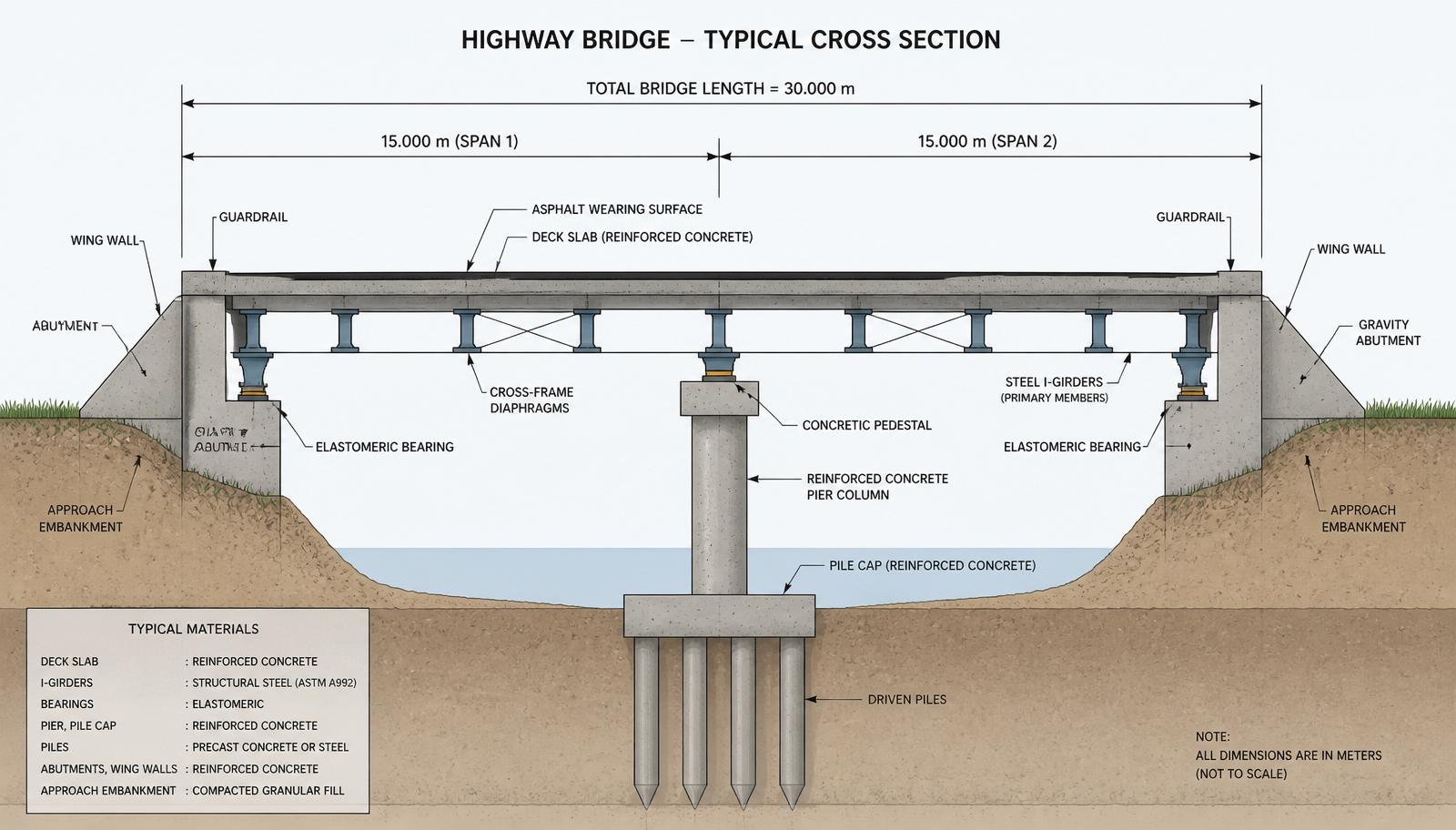
Every bridge you will design, inspect, or rate breaks down into the same small set of load-carrying elements. Learning their names, their purpose, and the practical construction issues that go with each is the vocabulary you will use for every conversation with a contractor, DOT reviewer, or client for the rest of your career. This section walks the anatomy top-down — from the wearing surface a car actually drives on, through the girders and bearings, down into the pier, and finally into the foundation.
1. Superstructure vs. substructure — the load path
The single most important idea in bridge engineering is the load path: every wheel load, every pound of self-weight, and every gust of wind must find a continuous path from where it is applied down to competent soil or rock. The bridge is divided into two families of parts that pass this load like a bucket brigade:
- Superstructure — everything above the bearings that carries the roadway: wearing surface, deck slab, primary members (girders / stringers), and secondary members (diaphragms, cross-frames, cover plates, stiffeners). It gathers vehicular loads and delivers them to a discrete set of bearing points.
- Substructure — everything from the bearings down: pedestals, cap beams, piers, abutments, and foundations (spread footings, drilled shafts, or driven piles). It gathers bearing reactions and spreads them into the ground under an allowable pressure.
2. The wearing surface — the sacrificial layer
The wearing surface is a sacrificial layer poured or laid on top of the structural deck. It protects the deck from tire abrasion, chloride ingress (from de-icing salt and coastal spray), UV, and the hydraulic action of tires driving through standing water. Two families are used on US bridges today:
- Bituminous — 50–75 mm of hot-mix asphalt over a waterproofing membrane bonded to the deck. Cheap, fast to place, easy to mill and replace, but the membrane failure rate governs long-term deck durability.
- Latex-modified concrete (LMC) — a 30–50 mm high-density concrete overlay bonded monolithically to the structural deck. More expensive, higher fatigue resistance, typical service life of 25+ years on interstate bridges.
Because the wearing surface is renewable — most agencies replace it two or three times over a 75-year bridge life — AASHTO classifies it as a separate load DW with the higher load factor γDW = 1.50 in Strength I, versus γDC = 1.25 for the permanent structural dead load. That difference exists because overlays often end up 30–50% thicker than the original design as pavement is added over the years.
3. The deck slab — the structural driving surface
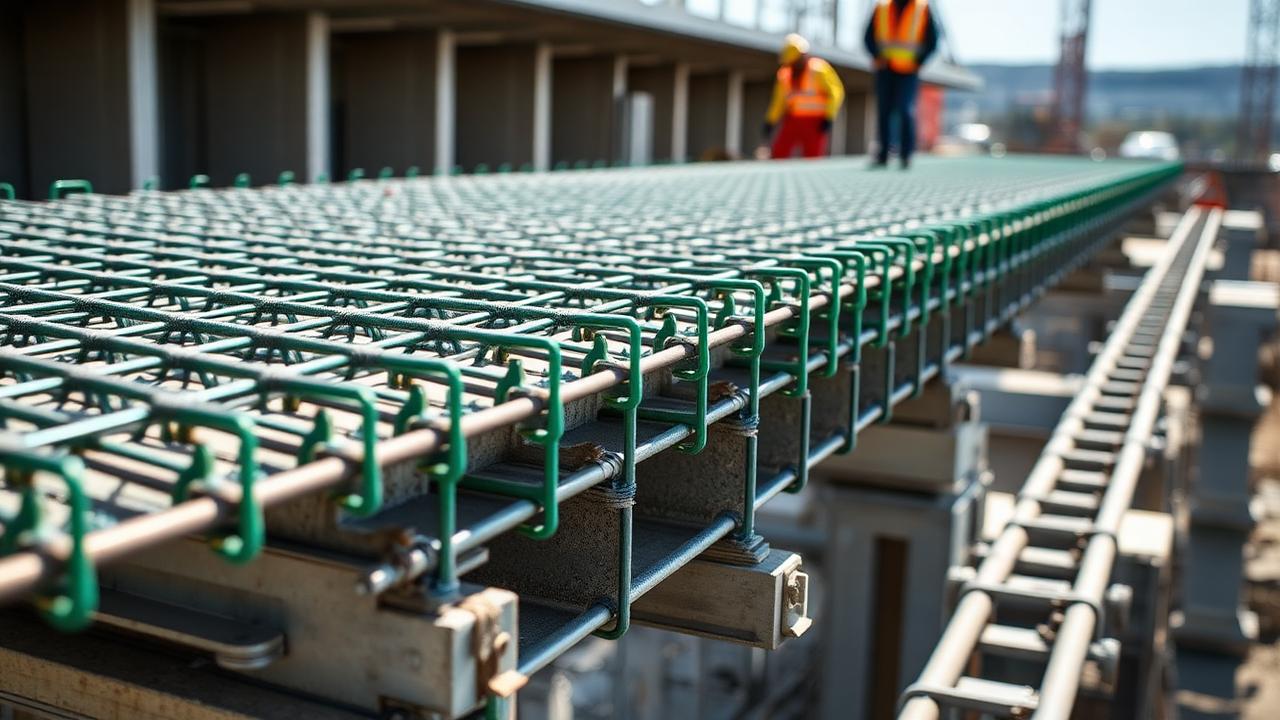
Below the sacrificial wearing surface sits the structural deck slab itself — typically a 200–250 mm reinforced concrete slab cast on stay-in-place metal forms spanning between the girders. Its job is threefold: (i) carry the wheel load between girders in transverse bending, (ii) distribute concentrated tire loads to several girders through membrane action, and (iii) act compositely with the girders as the top flange of the overall girder section, adding a huge amount of moment capacity to the composite girder.
Reinforcement is placed in two mats: a top mat resists negative bending over the girders (and takes the salt-water attack, so it is almost always epoxy-coated — the green bars in the photo), and a bottom mat resists positive bending in mid-panel. Typical spacings are 150–200 mm each way. The deck slab is the shortest-lived structural element on the bridge — national inventories show a mean deck life of 35–45 years before deep rehabilitation.
4. Primary members — girders and stringers
Primary members are the load-carrying beams that span between piers or abutments. They collect the deck reactions and deliver them to the bearings. In US practice you will see three families:
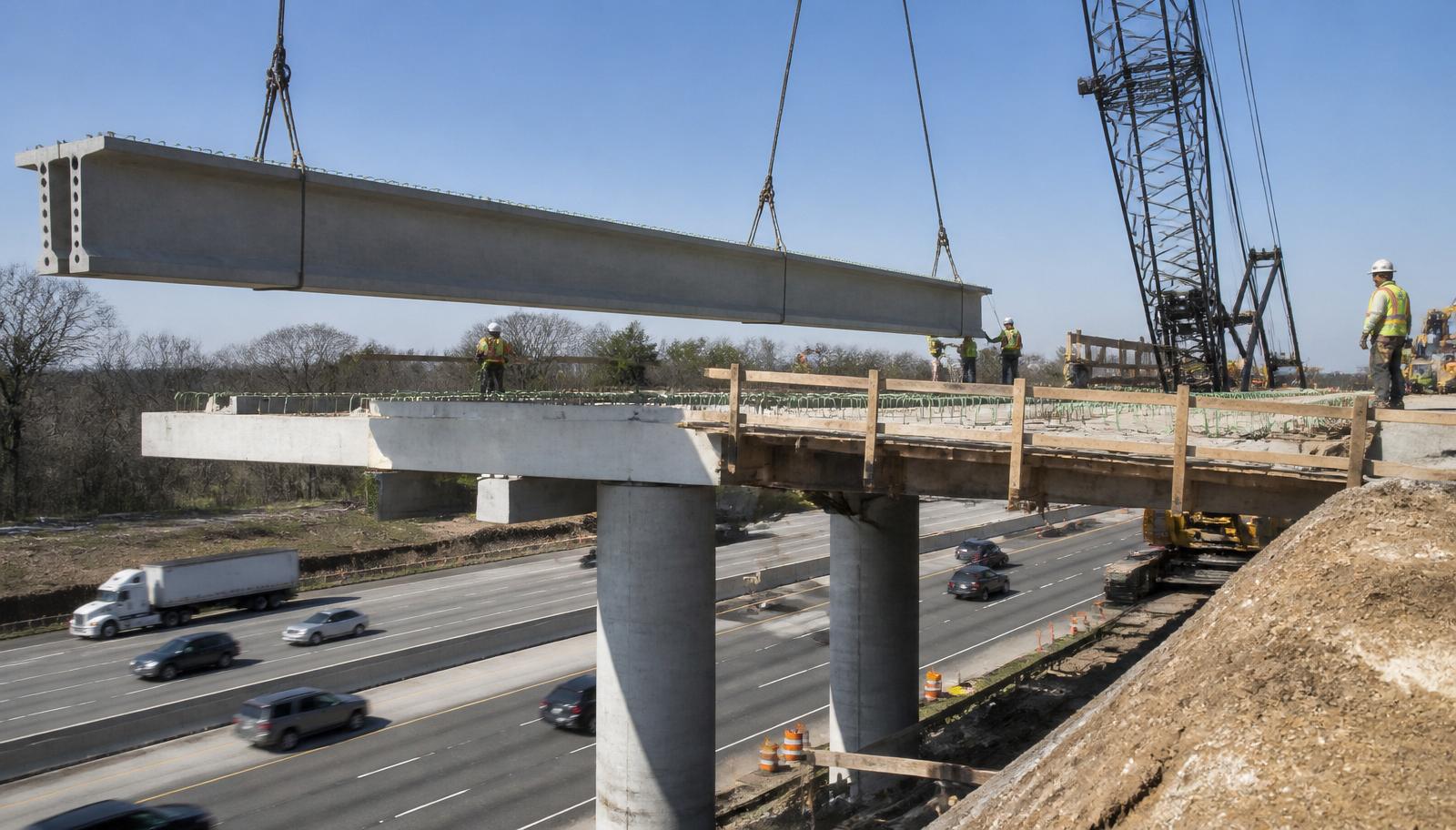
- Prestressed concrete I-girders (AASHTO Types II–VI, Bulb-T, Florida FIB) — precast in a yard, trucked to site, and set with a crane. The workhorse for 20–60 m simple spans. Fast erection, low maintenance, but limited to straight or gently curved alignment.
- Steel plate girders and rolled beams — welded I-sections tailored to the moment envelope. Handle curved alignment, heavy skew, and long spans (30–130 m) but need painting and periodic fatigue inspection.
- Concrete or steel box girders — closed-cell sections with far higher torsional stiffness. Used on curved elevated freeways and for segmental construction from 40 m up to 250+ m.
On multi-girder bridges the girders are laid out at a spacing of 2.4–3.7 m so that the deck slab design becomes a repetitive one-way transverse problem. The word stringer is used for the same idea in truss and floor-beam systems: a stringer is a longitudinal beam supported by transverse floor-beams, which in turn frame into the truss chord.

5. Secondary members — diaphragms, cross-frames, stiffeners
Secondary members do not carry the primary bending moment, but the bridge cannot function without them. Their job is to tie the girders together into a system:
- Diaphragms — solid transverse beams (concrete diaphragms in prestressed girder bridges, or bolted channel diaphragms in shallow steel girders) placed at supports and at mid-span. They distribute wheel loads laterally to adjacent girders, share torsional reactions, and stabilize the girders against lateral-torsional buckling during erection and service.
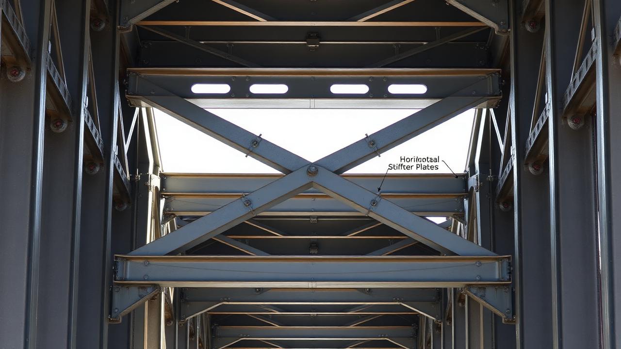
- Cross-frames — X- or K-shaped bracing of steel angles bolted between the webs of steel plate girders (visible in the photo). Function is the same as a diaphragm but they are lighter and easier to fabricate for deep girders. On curved girder bridges, cross-frames are primary load-carrying members because they resist the twist of the curve.
- Cover plates — extra plates welded to the flanges of a rolled steel beam in the high-moment region only. They add capacity where the moment demands it without paying for a heavier section end-to-end. Historic detail; new designs prefer welded plate girders because cover-plate weld terminations are notorious fatigue points.
- Stiffeners — vertical or longitudinal plates welded to the web of a steel plate girder. Transverse (vertical) stiffeners prevent web shear buckling, especially near bearings and at cross-frame locations. Longitudinal stiffeners are used on deep girders to push up the web-bend-buckling limit.
6. Substructure — piers, bents, and abutments
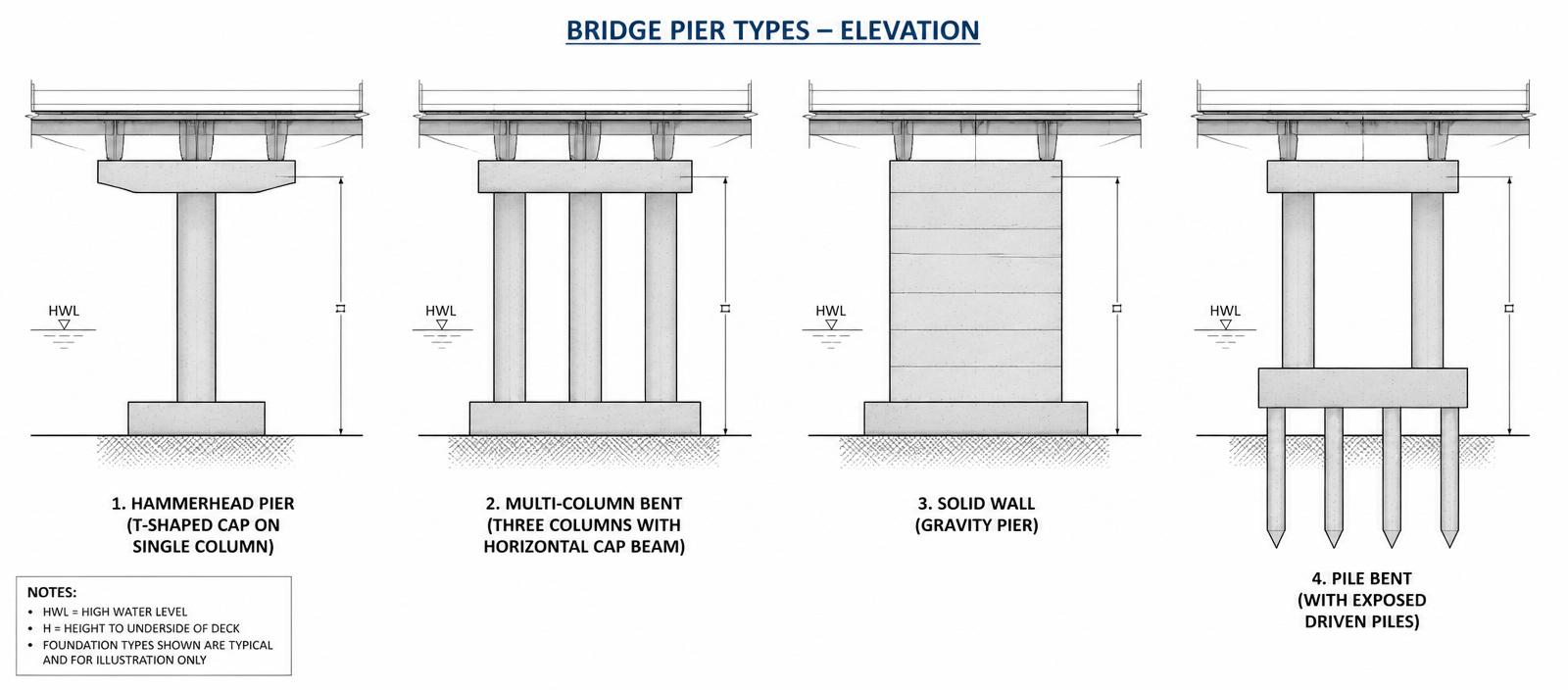
The choice of pier type is driven by three practical constraints: (i) the height of clearance that must be maintained beneath the deck, (ii) the depth and velocity of water at the site (which drives scour design — see Ch. 14), and (iii) the horizontal loads (wind, ship impact, seismic) the pier must resist. The four types you will see 95% of the time are:
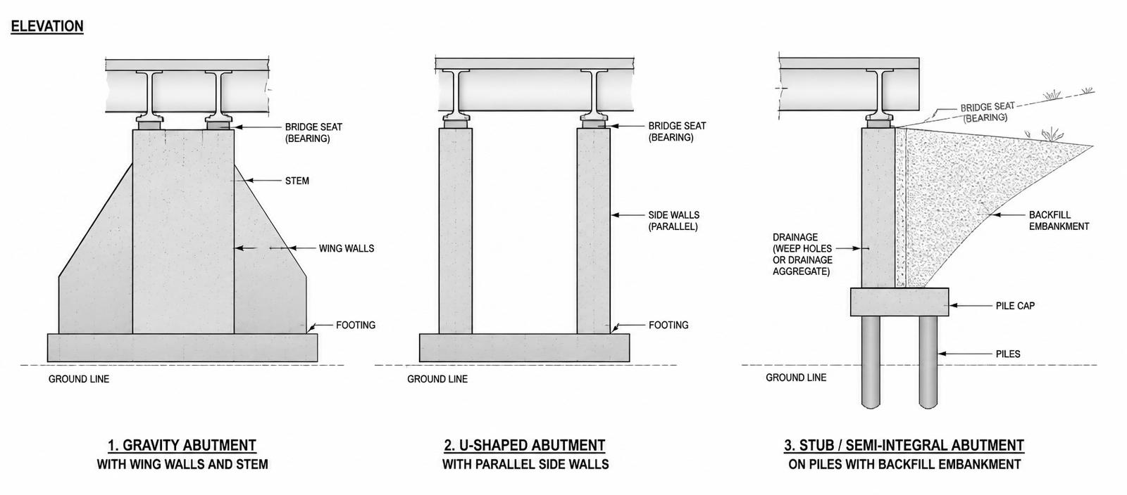
Abutments serve two jobs at once: they support the end reactions of the superstructure, and they act as retaining walls holding back the approach embankment. Three configurations dominate:
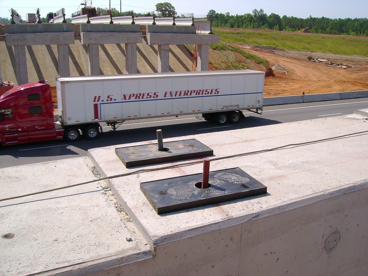
Between the girder and the top of the pier or abutment sits a pedestal — a plain-concrete block, usually 100–200 mm high, that raises the bearing off the concrete surface so ponding water cannot sit against it. Above the pedestal, a bearing(elastomeric pad, pot, or rocker/pin) accommodates the rotations and translations produced by live load, temperature, creep, and shrinkage. Bearings are the single most inspected element on the bridge — they wear out, and their replacement drives the deck-joint replacement schedule.
7. Deck joints — where movement is absorbed
Concrete and steel both change length with temperature (approximately α = 11 × 10⁻⁶ /°C for steel and 10 × 10⁻⁶ /°C for concrete). Over a 50 m simple span through a 60 °C temperature range the deck grows and shrinks about ±16 mm. Add creep and shrinkage of the concrete and you routinely need to accommodate ±25 mm of longitudinal movement at each end of the span. The deck joint is the detail that absorbs it.
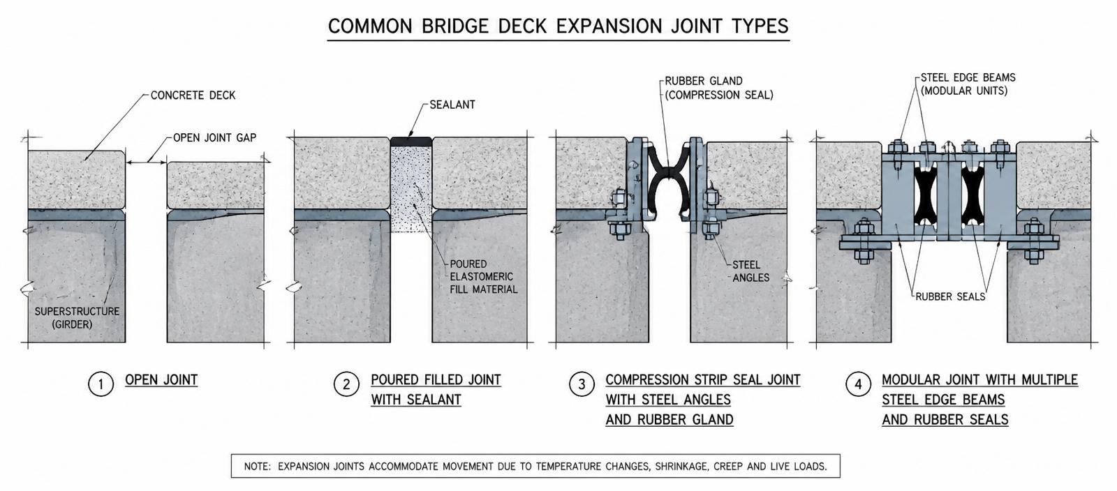
Selection is a trade-off between movement capacity, water-tightness, ride quality, and life-cycle cost. Every joint you specify becomes a maintenance item — the table below summarises the honest disadvantages of each family so you can pick the one whose failure mode you can live with.
| Joint type | Movement | Disadvantages / failure mode |
|---|---|---|
| Open (formed) joint | up to ±25 mm | Leaks water, salt, and debris directly onto the bearings, pedestal, and pier cap. This is the single largest cause of pier and bearing corrosion in the US inventory.Noisy under traffic. Debris clogs the gap and locks the joint, causing spalls at the arris. Prohibited on new bridges by most DOTs. |
| Compression seal (neoprene) | ±25 to ±40 mm | Seal takes a permanent set after a few years and no longer expands to fill the gap — loses water-tightness. Debris punctures the neoprene. Snowplow blades catch and rip the seal. Very sensitive to the width of the gap at installation temperature; if the gap is wrong the seal falls out. Life ≈ 10 – 15 years. |
| Strip / poured (silicone) seal | ±40 mm | Requires meticulous surface preparation; adhesion to concrete is the failure mode. Silicone tears at re-entrant corners. UV degrades the exposed lip. Cannot be snow-plowed heavily. Life ≈ 8 – 12 years, but very cheap to replace. |
| Finger joint (steel plates) | ±100 mm | By itself is not watertight — must be paired with a drainage trough beneath, which itself clogs with debris and corrodes. Fingers bend under wheel impact and become a hazard to motorcycles / bicycles. Bolt heads work loose from cyclic impact — a leading cause of ride-quality complaints. |
| Modular (multiple-seal, steel beams) | ±150 to ±1000 mm | Most expensive family — 5–10× a compression seal per lineal meter. Very high number of fatigue-critical welded details; support-bar cracking is a recurring failure. Very loud under truck traffic (drums the deck). Requires proprietary rehab crews and long lane closures. Failure of any one seal lets water reach the bearings below. |
| Asphalt plug (elastomeric-binder) | ±25 mm | Rutting and shoving under heavy truck braking. Softens in summer heat and cracks in deep cold — climate-limited. Very short life (5 – 8 years). Cannot bridge the gap at the abutment / approach-slab interface where rotation dominates. |
| Jointless / integral abutment | n/a — joint removed | Cheapest to maintain but transfers all thermal movement into the abutment piles as cyclic bending → fatigue and soil ratcheting behind the abutment. Approach-slab cracking is the classic symptom. Practically limited to total bridge lengths under ≈ 100 m (steel) or 180 m (concrete). |
Where possible, modern practice eliminates the joint entirely by making the deck continuous over the piers (link slab, jointless bridge, or integral abutment). Every joint you can remove is one less maintenance-nightmare item and one less path for chloride-laden water onto the bearings.
8. Span-length terminology
- Span > 6 m ⇒ classified as a bridge (AASHTO / FHWA definition)
- Span < 6 m ⇒ classified as a culvert
- Short span: 6 – 30 m · Medium span: 30 – 100 m · Long span: > 100 m
9. The family of structural systems
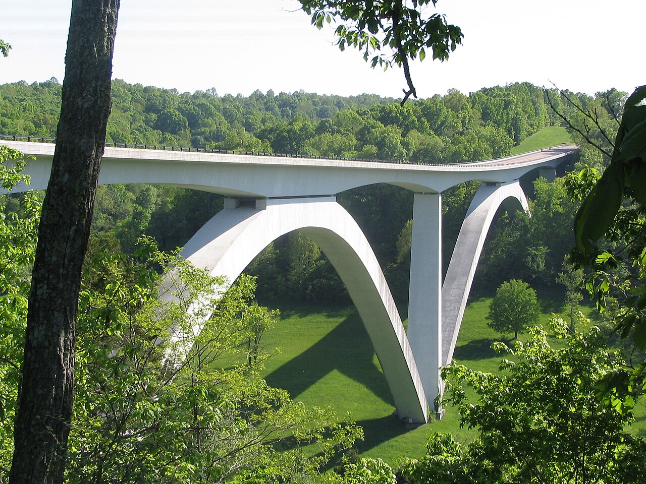
Bridges are classified four independent ways: by traffic (highway, pedestrian, rail, transit, utility), by the position of traffic (deck, through, half-through), by material (concrete, steel, timber, FRP), and — most importantly for design — by structural system. Each system has a practical span range within which it is the economic choice.



| System | Practical span (m) | Where it wins on cost |
|---|---|---|
| Reinforced concrete slab | 0 – 12 | Culverts, driveways over ditches |
| Precast concrete I-girder | 10 – 60 | Rural / suburban overpasses, straight alignment |
| Steel plate girder | 30 – 130 | Curved alignments, heavy skews, urban erection |
| Concrete box girder | 40 – 250 | Curved elevated freeway, segmental construction |
| Steel truss | 90 – 550 | Long clear span, heavy rail, cold-climate |
| Concrete arch | 90 – 300 | Deep valleys with competent rock abutments |
| Cable-stayed | 200 – 500 | Wide shipping channels, iconic urban gateways |
| Suspension | 500 – 2000+ | Only economical option beyond 900 m |
10. How the engineer picks a system
The system-selection matrix is a balance of ten factors, roughly in the order they usually govern:
- Span length — determines which families are even feasible
- Total bridge length and pier count
- Girder spacing — fewer deep girders vs many shallow girders
- Locally available materials and shipping cost
- Site conditions — foundations, vertical clearance, alignment curvature, shipping channel, urban footprint
- Speed and constructability — precast vs cast-in-place, gantry / launched deck options
- Contractor equipment and workforce experience
- Aesthetics and community context
- Access for future inspection and maintenance
- Initial + life-cycle cost — steel typically needs more paint / repair in coastal regions; concrete typically the least
Substructure-cost heuristic (from Dr. Efe's practice)
If the substructure is > 50% of total cost (deep water, tall piers, difficult foundations) → push spans longer so you build fewer piers.
If the substructure is < 25% of total cost (shallow water, competent near-surface bearing) → shorter spans are usually cheaper.
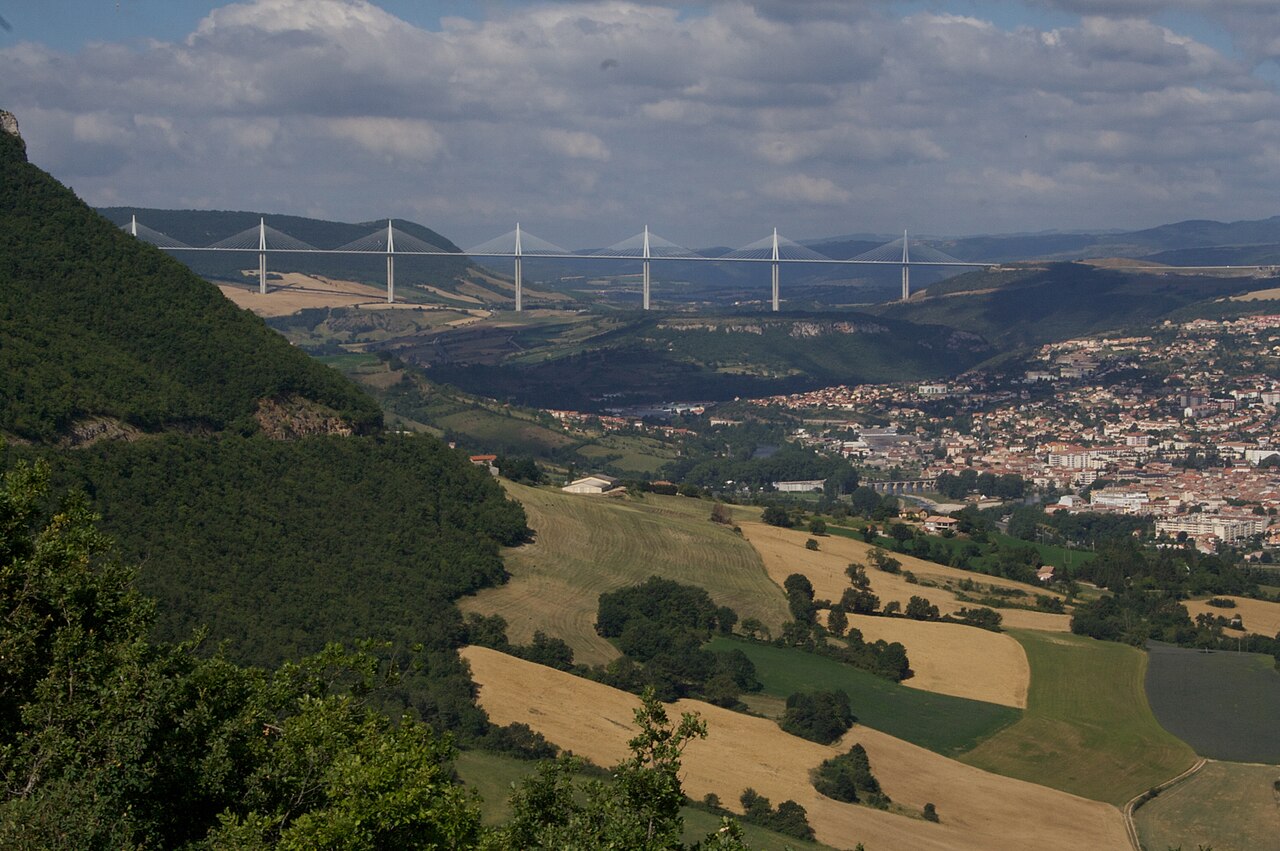
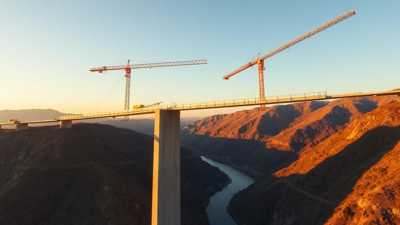
Site geometry can flip the answer in a heartbeat. A curved alignment eliminates precast I-girders entirely — you either accept the segmentation cost of precast segmental, or you cast in place. A required shipping channel of 200 m forces a single span across it, at which point cable-stayed often beats girder construction on total cost even though the unit cost per m² of deck is higher. In tight urban corridors, precast segmental pieces trucked in at night beat cast-in-place falsework schemes that block traffic for months. The Millau Viaduct (shown above) is a landmark example — the deck was launched incrementally from one abutment across temporary piers because the 270 m valley depth made conventional falsework impossible.
Key takeaway for this section
When you meet a new bridge for the first time — as an inspector, a load-rater, or a designer asked to widen it — the first thing you do is walk the load path in your head: wearing surface → deck slab → primary members → secondary members → bearings → pier cap → column → footing → soil. If you cannot name every element in that chain, you cannot check that every link is safe.
1.2 — Bridge engineering in the United States
A short history
A discourse on the history of bridges usually begins with a log across a small stream or vines suspended above a deep chasm, then the stone arch of the Roman engineers of the second and first centuries BC, the elegant Renaissance bridges of Europe, and finally the cast iron, wrought iron, and steel of the Industrial Revolution. Rather than repeat that history here, this section highlights a few bridges typical of those found in the United States, organized by structural material and system.
1.2.1
Stone arch bridges
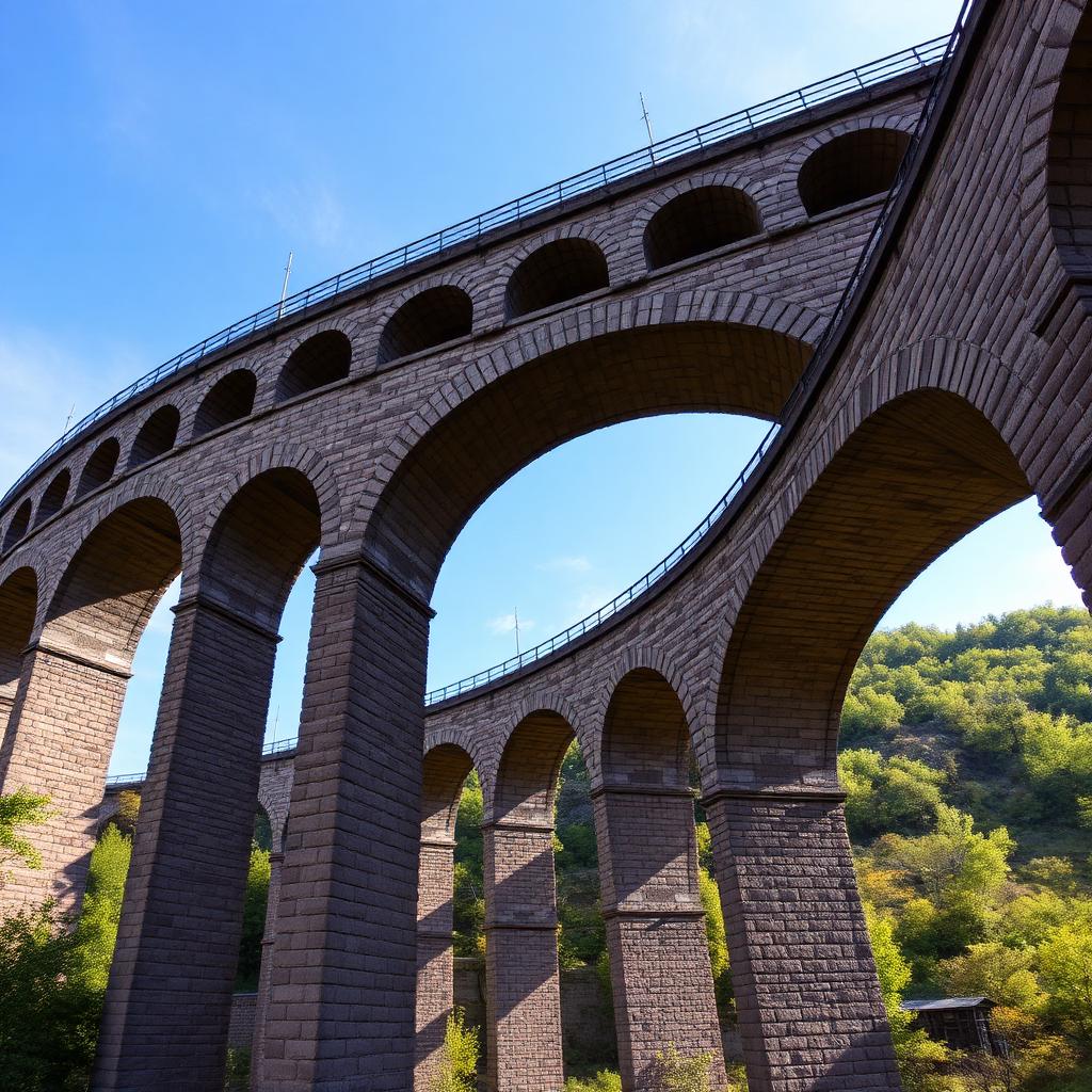
The Roman engineers utilized the semicircular arch and left a heritage of engineering works we still marvel at today. The oldest surviving Roman stone arch bridge dates from the ninth century BC (Smyrna, Turkey), and archaeologists have found arched vaults from the fourth millennium BC at Ur. In the United States, one of the earliest stone arch bridges is the Frankford Avenue Bridge over Pennypack Creek, built in 1697 on the road between Philadelphia and New York — a three-span, 73-ft (23-m) bridge that is the oldest bridge in the United States still serving a highway system (Jackson, 1988).
Stone arch bridges were labor intensive and never as popular here as in Europe, but with the rise of the railroads in the mid-to-late nineteenth century they provided the necessary strength and stiffness. Two impressive examples are the Starrucca Viaduct (Lanesboro, PA, 1848 — 1,040 ft with 17 arches of 50 ft) and the James J. Hill Stone Arch Bridge (Minneapolis, 1883 — 2,490 ft, originally 23 arches across the Mississippi below St. Anthony Falls).
Why arches, not beams, in stone
1.2.2
Wooden bridges
Early American bridge builders — Timothy Palmer, Lewis Wernwag, Theodore Burr, and Ithiel Town — began as millwrights or carpenter-mechanics. They had no clear conception of truss action, and their bridges were highly indeterminate combinations of arches and trusses (Kirby and Laurson, 1932). They learned to increase clear spans with the king-post system or trussed beam and appreciated the arch form because wood joints transfer compression more efficiently than tension.
To protect the timber from alternating wet–dry cycles that cause rot, wooden bridges were roofed — hence the classic covered bridge. Covered bridges gave the added benefits of keeping snow off the deck (which sometimes meant crews had to pave the deck with snow because everyone travelled by sleigh) and calming horses that would otherwise be frightened by open water below.
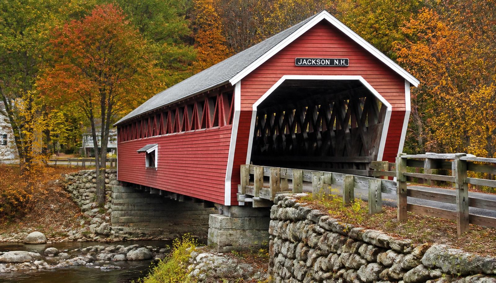
Ithiel Town patented the lattice truss in 1820 — strong top and bottom chords with a web of prefabricated lattice members of identical length, stiff enough that an arch was no longer required. Colonel Stephen H. Long in 1829 built the first American highway–railroad grade separation using a paneled truss with counterbraced web members. The concept of web panels that Long introduced is directly ancestral to the modern modified compression field theory (Ch. 7) and the tension-field action (Ch. 8) methods used today.
1.2.3
Metal truss bridges
Wooden bridges served the horse-drawn wagon well, but the railroads brought heavier loads and longer spans. Wrought-iron rods first replaced wooden tension members; then cast iron replaced wooden compression members, completing the transition to an all-metal truss. Key patents:
- Howe truss — William Howe, 1841. Wrought-iron vertical rods with turnbuckles hold wooden diagonals in compression against cast-iron angle blocks.
- Pratt truss — Thomas and Caleb Pratt, 1844. Main diagonals in tension; the most commonly built type in the U.S. for simplicity, stiffness, constructability, and economy.
- Bowstring arch and double-intersection Pratt — Squire Whipple, 1841.
Whipple was also a graduate of Union College (1830) and in 1847 published the first American treatise on bridge stress analysis, A Work on Bridge Building. Herman Haupt (West Point 1835) published General Theory of Bridge Construction in 1851. These two texts provided the theoretical basis for selecting cross sections against dead and live loads. Just as important was the parallel development of testing machines — from the 10-ton Franklin Institute machine (1832) to the 2,000-ton American Bridge Company machine (1904, Ambridge, PA) that let engineers actually verify column-load curves and material strengths.
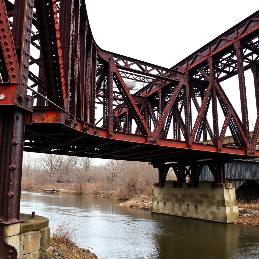
The lesson of the Ashtabula (1876) and Quebec (1907) failures
1.2.4
Suspension bridges
With tall towers, slender cables, and tremendous spans, suspension bridges appear as ethereal giants stretching out to join opposite shores. James Finley erected the first modern suspension bridge in 1801 — a 70-ft wrought-iron chain over Jacob's Creek near Uniontown, Pennsylvania — and patented the stiffened level floor in 1808. But John A. Roebling brought the form to maturity: the Niagara River Bridge (1855, 825 ft), the Cincinnati Suspension Bridge (1867, 1,057 ft), and the Brooklyn Bridge (1883, 1,595 ft).

| Bridge | Site | Designer | Clear Span, ft (m) | Date |
|---|---|---|---|---|
| Wheeling | West Virginia | Charles Ellet | 1,010 (308) | 1847 |
| Cincinnati | Ohio | John Roebling | 1,057 (322) | 1867 |
| Brooklyn | New York | John & Washington Roebling | 1,595 (486) | 1883 |
| Williamsburg | New York | Leffert Lefferts Buck | 1,600 (488) | 1903 |
| Ben Franklin | Philadelphia | Modjeski & Moisseiff | 1,750 (533) | 1926 |
| George Washington | New York | Othmar Ammann | 3,500 (1,067) | 1931 |
| Golden Gate | San Francisco | Strauss, Ellis, Moisseiff | 4,200 (1,280) | 1937 |
| Verrazano-Narrows | New York | Ammann & Whitney | 4,260 (1,298) | 1964 |
Table 1.1 — Long-span U.S. suspension bridges (after Wai-Fah Chen & Duan; Barker & Puckett). The George Washington Bridge nearly doubled the world record when it opened.
Aeroelastic instability — the Tacoma Narrows lesson
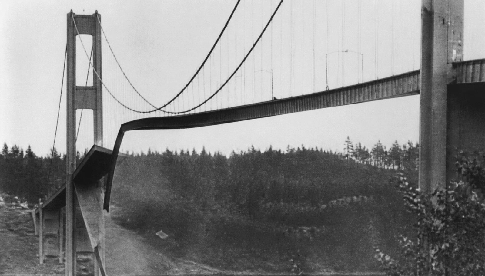
Leon Moisseiff designed the 2,800-ft Tacoma Narrows Bridge (1940). Its plate-girder stiffening system had a depth-to-span ratio of 1:350 — compare to 1:40 for Williamsburg and 1:164 for Golden Gate. It self-destructed in a modest wind on November 7, 1940 — almost a re-run of the 1854 wind failure of Wheeling. The lesson: economy in the stiffening system cannot come at the price of aerodynamic stability. Every long-span bridge since is checked in a wind tunnel.
1.2.5
Metal arch bridges
Arch bridges are aesthetically pleasing and can be economically competitive when the foundation soils can resist the horizontal thrust. The first iron arch bridge in the United States was built in 1839 across Dunlap's Creek at Brownsville, Pennsylvania, on the National Road — five tubular cast-iron ribs spanning 80 ft between fixed supports — still in service today.
One of the most significant U.S. bridges is the Eads Bridge across the Mississippi at St. Louis, completed by James Buchanan Eads in 1874 after seven years of construction. Its two 502-ft side arches and 520-ft center arch were built by balanced cantilever — falsework in the river was impossible. Eads placed the foundations on bedrock at depths up to 136 ft using pneumatic caissons (a technique he learned in France); the resulting cases of "caisson's disease" prompted the first medical protocols for decompression. Eads also insisted on chrome-steel with a 50-ksi elastic limit and 120-ksi ultimate — an unprecedented material specification for its time that set the benchmark for future standards (Brown, 1993).

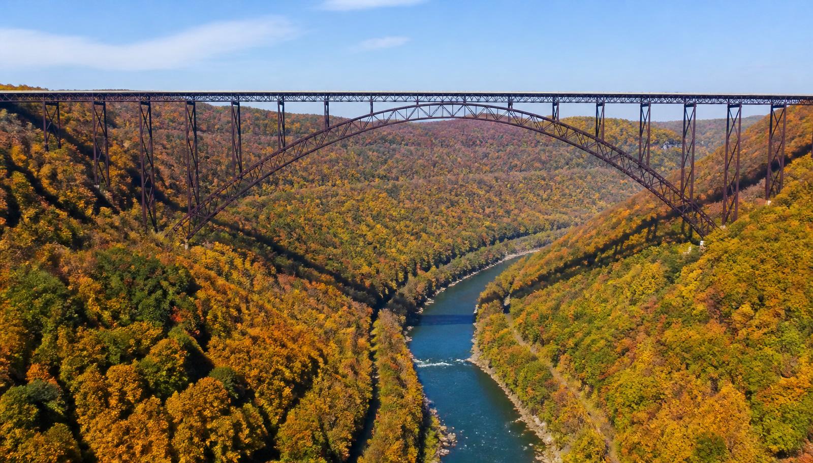
Long-span steel deck arches after Eads include the Hell Gate Bridge (New York, 977 ft, 1917), the Bayonne Arch Bridge (NY/NJ, 1,675 ft, 1931), and the New River Gorge Bridge near Fayetteville, West Virginia — the longest steel arch in the United States at 1,700 ft (Michael Baker, Jr., Inc., 1978).
1.2.6
Reinforced and prestressed concrete bridges
Portland cement was patented by Joseph Aspdin in 1824 and produced in the United States beginning around 1871 (Taylor, PA and Millen, IN). The first steel-bar reinforced concrete bridge in the U.S. was Ernest Ransome's 20-ft-span Alvord Lake Bridge in Golden Gate Park, San Francisco (1889) — 64 ft wide, still in service. Reinforced concrete arch bridges proliferated in parks because their classic stone-arch appearance fit the surroundings.
The first prestressed concrete girder bridge in the United States was the Walnut Lane Bridge in Philadelphia (1950). After its success, prestressed concrete girders became the workhorse for highway interchanges and grade separations across the interstate system. In Maryland, MDOT SHA defaults to prestressed AASHTO / PCI bulb-tee girders for spans in the 60–160 ft range on state highways.
1.2.7
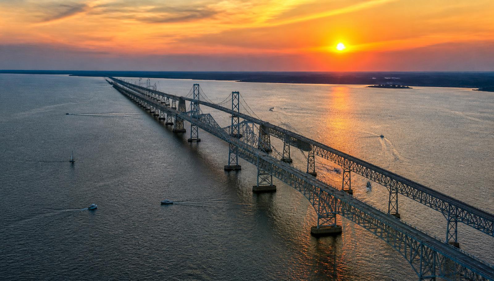
Girder bridges
Girder bridges are the most numerous of all highway bridges in the United States. Their contribution to the transportation system often goes unrecognized because the great suspension, steel arch, and concrete arch bridges get the attention. Girder spans seldom exceed 500 ft (150 m), and a majority are under 170 ft (50 m) — yet they carry the vast majority of vehicle-miles travelled in the U.S. every day.
1.2.8
Closing remarks
Bridge engineering in the United States has come a long way since those early stone arch and wooden truss bridges. It is a rich heritage, and much can be learned from the early builders who overcame what seemed insurmountable difficulties. Sometimes by the sheer power of their will, they completed projects we still view with awe. The challenge for today's bridge engineer is to follow in their footsteps — and to create and build bridges that other engineers will write about 100 and 200 years from now.
1.2.9 — Deck materials
Timber, concrete, and steel: the three workhorses of the riding surface
The deck is the structural element that receives the wheel loads directly and transfers them to the supporting girders. Its material choice drives self-weight, durability, construction speed, ride quality, and future maintenance cost. In North American practice three materials dominate: timber, concrete, and steel. Each carries a different history, mechanical behaviour, and failure mode.
1.2.9.a
Timber decks
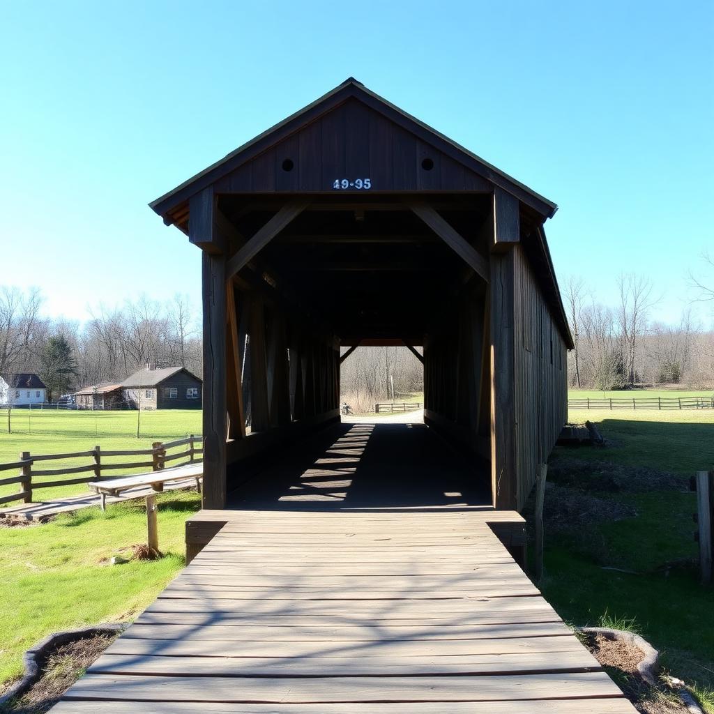
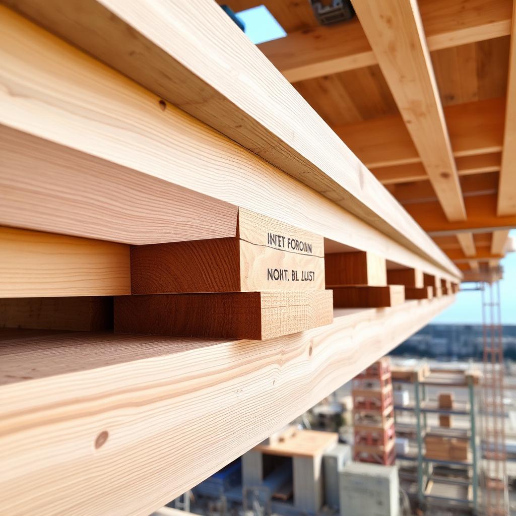
Timber is the oldest deck material and remains competitive on low-volume rural routes and short spans (typically ≤ 20 ft plank, ≤ 40 ft glulam). Two families are used today:
- Sawn-lumber plank decks — nailed or bolted transverse planks over longitudinal stringers. Simple, field-repairable, but rides rough and channels water into the substructure.
- Glued-laminated (glulam) panel decks — factory-laminated Douglas fir or Southern pine panels post-tensioned transversely with high-strength bars. Behaves as an orthotropic plate; ride quality approaches concrete.
Design is governed by AASHTO LRFD Section 8 and the NDS Supplement. Live-load distribution uses the equivalent-strip approach with an impact-reduction factor(IM is taken as zero for wood — timber's damping absorbs the dynamic component, per §3.6.2.3).
Advantages of timber
Disadvantages of timber
1.2.9.b
Concrete decks
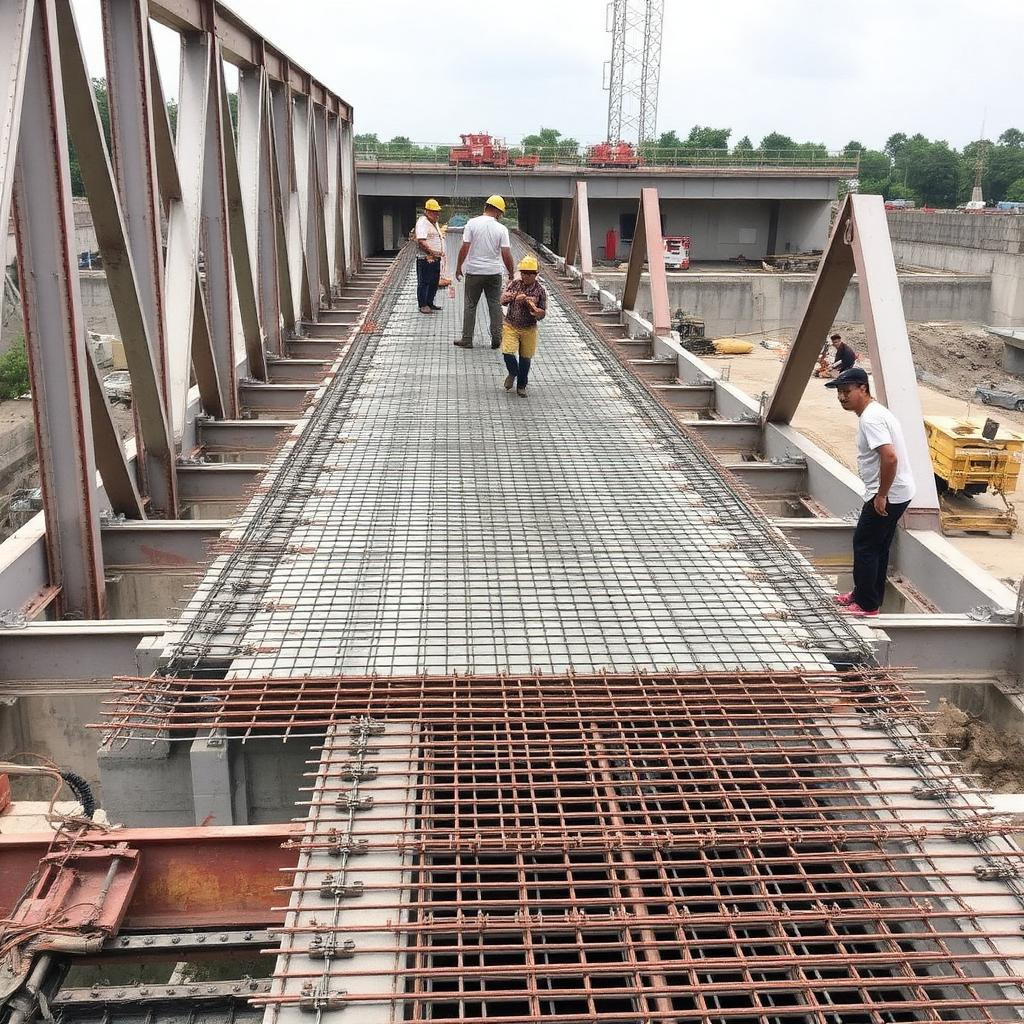
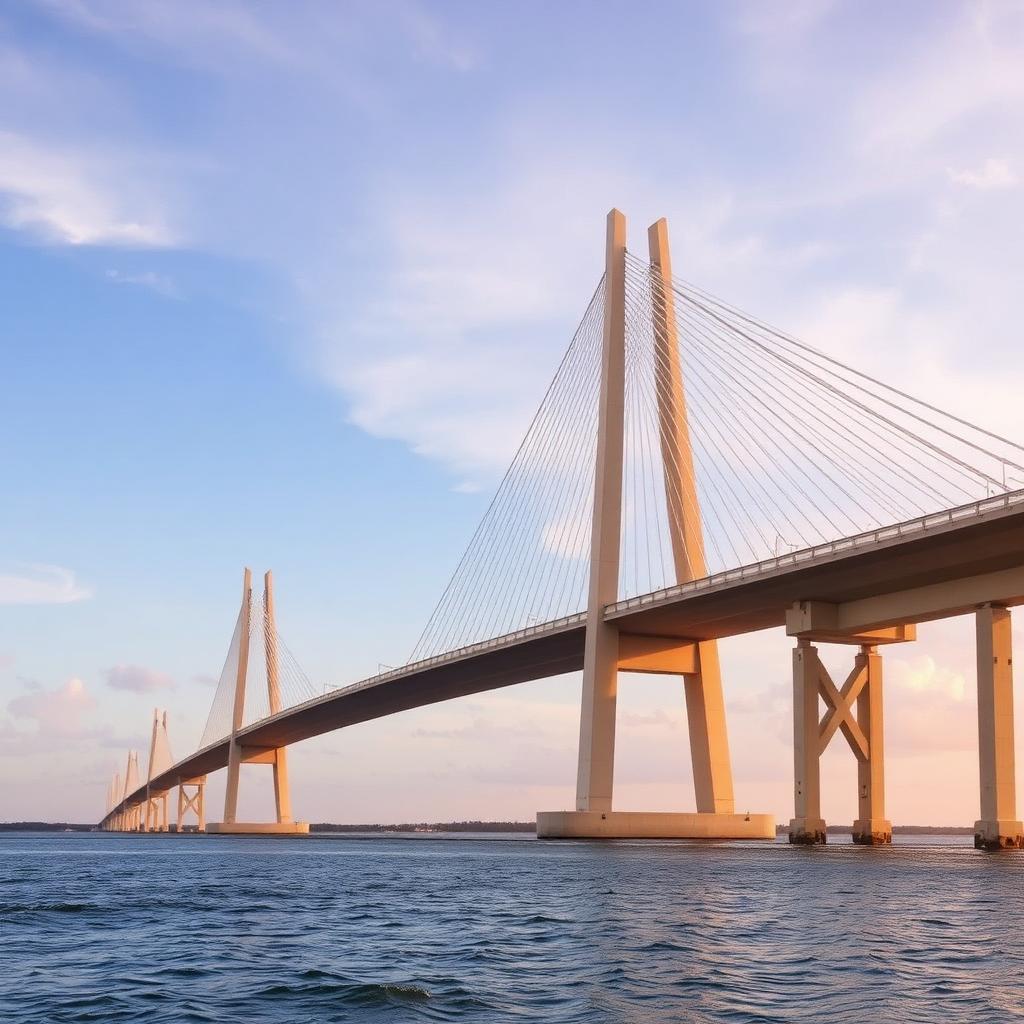
Concrete is the dominant U.S. deck material — roughly 85 % of the National Bridge Inventory (FHWA, 2023). Four sub-types deserve mention:
- Cast-in-place (CIP) reinforced concrete — typical thickness 8–9 in, f′c = 4 ksi, εᴮ epoxy-coated or stainless bars. Designed by AASHTO's equivalent-strip method (§4.6.2.1) or the empirical design method that exploits internal arching action (§9.7.2).
- Precast concrete deck panels — 3–4 in-thick stay-in-place panels topped with a CIP composite pour; used for accelerated construction.
- Full-depth precast panels — 8-in panels post-tensioned longitudinally; connected to girders through pockets grouted with UHPC.
- Prestressed concrete decks — pretensioned or post-tensioned; common in segmental box girders and long-span cable-stayed bridges.
Advantages of concrete
Disadvantages of concrete
1.2.9.c
Steel decks
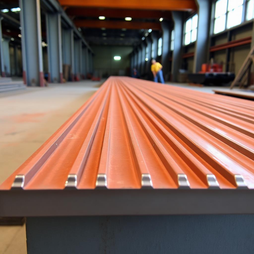
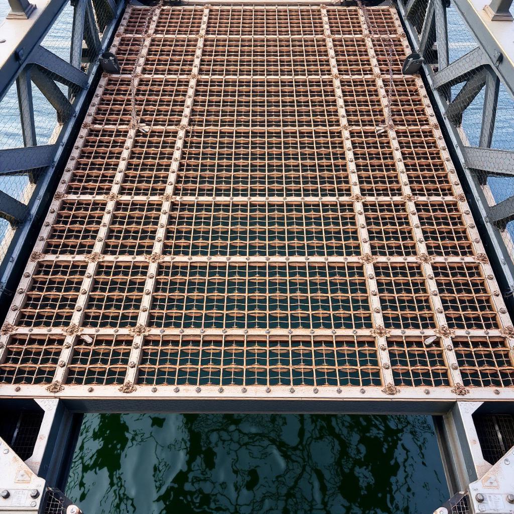
Steel decks are chosen where self-weight is critical: long-span, movable, and rehabilitation projects that must not add dead load to existing girders. The three common forms are:
- Orthotropic-plate deck — a stiffened steel plate that serves simultaneously as the top flange of the girders, the deck, and (with wearing surface) the riding surface. Weighs ≈ 25 % of an equivalent RC deck. Used on Golden Gate re-deck, Verrazzano, San Mateo-Hayward.
- Open steel grid — welded rectangular bars forming an open grating; wheel loads bear directly on the steel. Very light (≈ 20 psf) but noisy and skid-prone in rain.
- Filled/partially-filled grid — the open grid is filled with concrete; combines light weight with a paved riding surface.
Advantages of steel
Disadvantages of steel
1.2.9.d
Side-by-side property comparison
| Property | Timber (glulam) | Reinforced concrete | Structural steel (orthotropic) |
|---|---|---|---|
| Unit weight, γ | ≈ 35 pcf | 150 pcf | 490 pcf (thin plate → 25 psf) |
| Modulus, E | 1,700 ksi | 3,600 ksi (f′c=4 ksi) | 29,000 ksi |
| Design tensile strength | Fb ≈ 2.4 ksi | rebar Fy = 60 ksi | Fy = 50–70 ksi |
| Typical deck thickness | 5–14 in panel | 8–9 in slab | ½–¾ in plate + ribs |
| Typical span capability | ≤ 40 ft | up to 15 ft between girders | up to 20 ft between girders |
| Dynamic load allowance IM | 0 % | 33 % (75 % on joints) | 33 % |
| Expected service life | 30–50 yr | 50–75 yr | 75–100 yr (with re-paint) |
| Primary failure mode | Decay, plate loosening | Rebar corrosion, spalling | Fatigue cracking, coating loss |
| Relative cost / sf (2024) | $45–70 | $55–90 | $150–250 |
| Embodied CO₂ | Negative (sequestered) | High | Very high (offset by longevity) |
1.2.10 — Innovations
New materials and construction methods reshaping practice
1.2.10.a
Fiber-reinforced polymer (FRP) decks and rebar
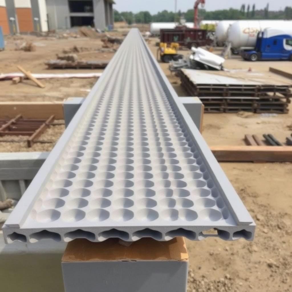
FRP composites — glass or carbon fibres in a polymer matrix — offer a corrosion-free alternative in aggressive environments (marine, chemical, high-salt). Two families:
- FRP deck panels — pultruded or vacuum-infused sandwich panels 4–8 in deep; γ ≈ 12–20 pcf, i.e., one-fifth of concrete. AASHTO published the LRFD Guide Specifications for FRP Vehicular Bridges (1st ed., 2018).
- FRP reinforcing bars (GFRP, CFRP) — replace steel rebar in concrete decks where chlorides are unavoidable (e.g., northern deck overlays). Covered by AASHTO's LRFD Bridge Design Guide Specifications for GFRP-Reinforced Concrete.
Where FRP wins
Where FRP still struggles
1.2.10.b
Segmental (precast/CIP) construction
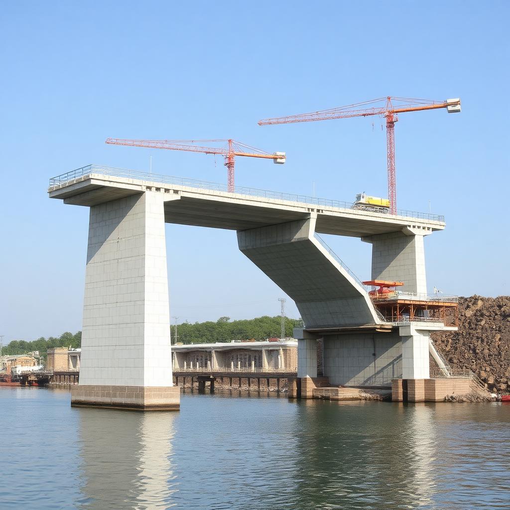
Segmental construction builds long-span concrete box girders from short precast or cast-in-place segments joined by longitudinal post-tensioning. The two erection variants are balanced-cantilever (segments hung symmetrically from a pier) and span-by-span (segments assembled on an underslung truss). Landmark examples: Sunshine Skyway, Seven Mile Bridge, and the U.S. 331 Choctawhatchee Bay Bridge.
- Eliminates falsework over navigable water, deep valleys, or live traffic.
- Repeatable factory-cast segments give tight quality control.
- Post-tensioning ducts must be perfectly grouted or corrosion of tendons — see the FDOT Ringling Bridge and the Mid-Bay Bridge inspection findings — becomes a life-cycle liability.
1.2.10.c
Accelerated Bridge Construction (ABC)
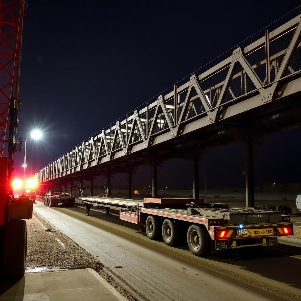
Accelerated Bridge Construction is FHWA's umbrella program for methods that reduce on-site closure from months to hours. Core techniques:
- Prefabricated Bridge Elements and Systems (PBES) — full-depth precast deck panels, precast pier caps, precast abutment stems, and even full superstructure modules.
- SPMT moves — a temporary bridge is built off-line on multi-axle transporters, then rolled into place during a weekend closure. Utah DOT's I-15 Sam White bridge (2011) set the North-American benchmark: a 354-ft, 2,400-ton superstructure moved 700 ft in one night.
- Lateral slide-in — the new bridge is built parallel to the existing one, then slid transversely onto the piers.
- Geosynthetic-Reinforced-Soil Integrated Bridge System (GRS-IBS) — abutments of alternating compacted fill and geotextile; suited to short-span local bridges.
1.2.10.d
Ultra-High-Performance Concrete (UHPC) connections
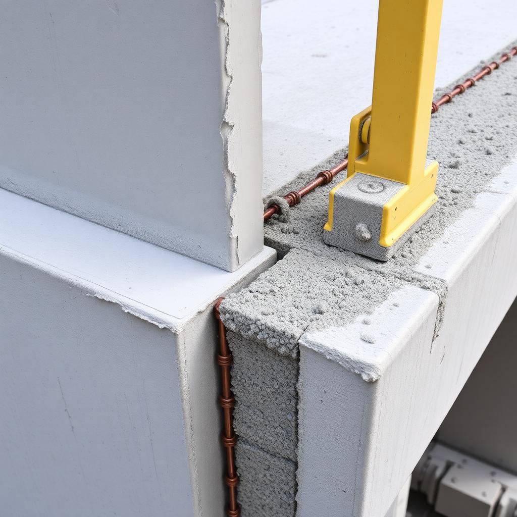
UHPC (f′c > 21 ksi, tensile strength > 1 ksi, fibre-reinforced) allows a 6-in lap splice to develop a #6 bar — one-third of the length required in conventional concrete. That single property has made full-depth precast panelconstruction economically viable and is now the FHWA-recommended detail for ABC deck-to-girder and panel-to-panel connections.
1.2.10.e
Other frontier technologies (brief)
- 3-D-printed concrete abutments and formwork — first live-load demonstration bridges in the Netherlands (Gemert, 2017) and Iowa DOT (2022).
- Shape-memory-alloy (SMA) reinforcement — self-centring seismic columns being piloted by Caltrans.
- Structural health monitoring (SHM) — fibre-optic strain sensors embedded in girders (e.g., the New I-35W in Minneapolis) feed a digital-twin model that updates load rating in real time.
- Bio-based and low-carbon binders — calcined-clay/limestone (LC³) and geopolymer concretes are moving from research into pilot deck pours.
Take-away
1.3 — Bridge specifications
From design-build to LRFD
For most bridge engineers it seems that bridge specifications have always been there — but that is not the case. Early bridges were built under a design-build contract awarded to the low bidder, who essentially wrote their own specifications. Some very good bridges were built, but some very poor ones were also built. Of the highway and railroad bridges built in the 1870s, one out of every four failed — a rate of about 40 bridges per year (Gies, 1963). The public lost confidence in the safety of crossing any bridge.
The turning point was the collapse of the Ashtabula Creek railroad bridge (Ohio, 29 December 1876) — a 175-ft Howe truss with cast-iron bearing blocks that gave way under an 11-car train in a snowstorm, killing 80. The investigation exposed a profession without design standards. It is ironic that an ASCE meeting concluded "the construction of the truss violated every canon of our standard practice" — at a time when there were no standards of practice.
Formal codification followed:
- 1894 — Theodore Cooper proposes his railroad-train loadings (adopted by AREA in 1903).
- 1914 — AASHO (American Association of State Highway Officials) is formed.
- 1921 — AASHO Committee on Bridges and Allied Structures organized.
- 1931 — Standard Specifications for Highway Bridges and Incidental Structures, 1st edition.
- 1963 — AASHO becomes AASHTO (adding "Transportation").
- 1970s — Load Factor Design (LFD) introduced as an alternative to working-stress design.
- 1986 — Subcommittee on Bridges and Structures initiates the LRFD study.
- 1994 — First edition of AASHTO LRFD Bridge Design Specifications.
- 2024 — 10th Edition (current) — the governing document for this course.
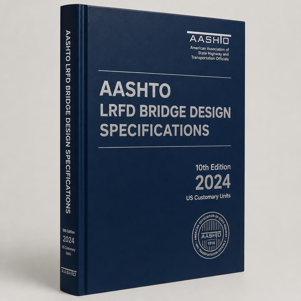
AASHTO LRFD Reference
1.4 — Failures that shaped practice
Learning from the record
Standards change fastest when they must. Every entry in Table 1.2 below reshaped the AASHTO specifications in the years that followed.
| Bridge / event | Year | Root cause | Effect on practice |
|---|---|---|---|
| Silver Bridge, Point Pleasant, WV | 1967 | Cleavage fracture in a single eyebar (stress-corrosion + corrosion-fatigue), non-redundant chain, 46 deaths. | National Bridge Inspection Standards (NBIS) established under the 1968 Federal Aid Highway Act — biennial inspections; National Bridge Inventory (NBI) created. |
| I-5 / I-210 interchange, San Fernando, CA | 1971 | Bridges designed for 4% dead-load lateral (~0.04 g); actual accelerations 0.33–0.50 g horizontal / 0.17–0.25 g vertical. Girders fell off short seats. | Seismic design forces include site, importance, and ductility factors; ductile detailing (closer hoops/spirals, anchorage requirements); larger seat widths; alternate load paths via seismic restrainers. |
| Sunshine Skyway, Tampa Bay, FL | 1980 | Bulk carrier Summit Venture lost the channel in a thunderstorm, rammed unprotected pier; 35 deaths. | AASHTO vessel-collision provisions (now §3.14) — pier protection systems, design vessel selection, annual frequency of collapse targets. |
| Mianus River Bridge, Greenwich, CT | 1983 | Corroded pin-and-hanger assembly (drainage failure) let a hanger walk off its pin; 3 deaths. | Detailed fracture-critical inspection procedures; pin-and-hanger assemblies effectively abandoned in new design; deck drainage detailing. |
| Schoharie Creek Bridge, NY Thruway | 1987 | Local scour at pier 3 on a spread footing without piles; missing riprap never replaced. 10 deaths. | Modern scour-prediction methods; mandatory underwater foundation inspection; redundancy in substructure load paths. |
| Cypress Viaduct, Loma Prieta EQ, CA | 1989 | Non-ductile column shear failure of a 1957-era double-deck viaduct; pancake collapse killed 42. | Caltrans Seismic Safety Retrofit Program; performance-based seismic design; column jacketing standards adopted nationally. |
Table 1.2 — Six failures that reshaped U.S. bridge specifications. Sources: NTSB reports (1970, 1981, 1984, 1988); Lew et al. (1971); Caltrans (2003). Full narratives are in the Case Studies section of this platform.
A common thread
Every failure in Table 1.2 involved either lack of redundancy, inadequate inspection, or a design event exceeding what the code then required. AASHTO LRFD 10th Ed. addresses all three — but only if the designer applies the framework honestly.
1.5 — Failures during construction
Erection engineering, temporary stability, and professional responsibility
A completed bridge and a bridge under construction are two different structures. In the finished state the load path is continuous, every member is braced by its neighbours, and the design engineer has spent months proving under AASHTO LRFD that every limit state is satisfied. During construction that same bridge passes through dozens of transient states — partial cantilevers, unshored girders, unstressed tendons, half-cast decks — and the loading is dominated by construction equipment (crawler cranes, launching gantries, form travellers) that the designer never saw. Statistically this is when most bridges fail. This section is not a list of collapses; it is an introduction to construction sequencing, temporary stability, erection engineering, and the professional responsibility that binds them.
1. Two different structures
The first thing a young engineer must internalise is that the finished-bridge model studied in class is only the final frame of a long movie. Every earlier frame is a different structural system, often less redundant and with a different governing limit state.
Finished bridge
Bridge during construction
2. Why bridges fail during construction
Post-collapse investigations by the NTSB, FHWA, and international counterparts converge on seven recurring causes. Any one of them can bring the structure down; most real collapses are the intersection of two or three.
Temporary instability
Construction sequence errors
Temporary overloading
Falsework failure
Connection failure
Foundation problems
Human error / communication
3. The construction load path
The clearest way to see the risk is to draw the load path twice — once for the crane lifting a girder into place, and once for the same girder in service. The finished path is short and redundant; the construction path is long, passes through temporarybearings, and often depends on a single crane mat or false-bent that was designed by the contractor, not the engineer of record.
During construction (crane pick)
Finished bridge (wheel load)
Notice the construction path has two extra links (temporary bearing and false-bent) and passes through a member the engineer of record may never have designed. Every extra link is a place the chain can break.
4. Major case studies
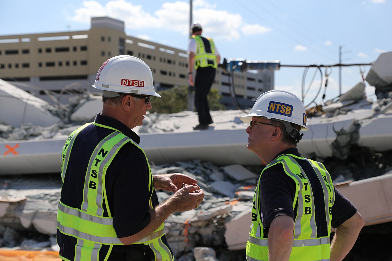
Case study
FIU–Sweetwater Pedestrian Bridge
Miami, FL, USA · 2018 · 6 killed, 10 injured
A 174 ft pre-cast concrete truss span built alongside SW 8th Street using Accelerated Bridge Construction (ABC) and moved into position with self-propelled modular transporters. Cracks up to 40 mm wide were photographed at the north diagonal-to-deck node two days before the collapse. Post-tensioning of the cracked diagonal was under way with the roadway open to traffic when the node failed and the span dropped onto vehicles below.
Timeline
10 Mar 2018 — Span moved into place using SPMTs; overnight closure of SW 8th Street.
13 Mar — Cracks reported at north diagonal; design team judges structure stable, does not close road.
15 Mar 09:00 — Peer-review call — 'not a safety concern.'
15 Mar 13:47 — Re-tensioning of diagonal #11 in progress; node fails; span collapses in <2 s.
Engineering lessons
- ABC does not eliminate the need for redundancy — the truss was non-redundant at the failed node.
- Cracks of that magnitude in a post-tensioned concrete member are a stop-work condition, full stop.
- Peer review must have authority to close the road. In this case it did not.
- Ethical obligation of the licensed EOR to disclose risk overrides schedule and cost pressure.
Case study
Quebec Bridge (first & second collapses)
Québec, Canada · 1907 & 1916 · 75 (1907) + 13 (1916)
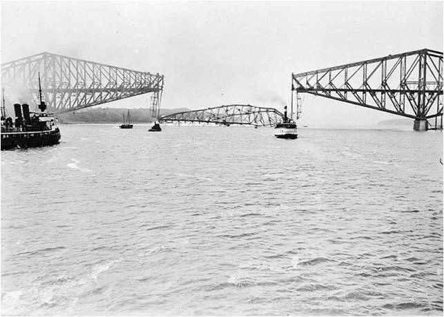
The world's longest cantilever span at the time (549 m). During erection the consulting engineer Theodore Cooper approved an increase in span length after fabrication had started, but the dead-load calculations were not revised. As the south cantilever grew, chord compression members began to buckle visibly. Cooper's telegram ordering work to stop arrived after the collapse. In 1916, during re-erection with a new design, the 5,000-tonne central span fell into the river while being hoisted because of a casting failure in a temporary lifting shoe.
Engineering lessons
- Dead load must be recalculated for every geometry change — never scaled by intuition.
- Compression-member buckling is the classic failure mode of long cantilevers under construction.
- The engineer of record must have physical presence and unambiguous stop-work authority.
- This disaster gave rise to Canada's 'Ritual of the Calling of an Engineer' (Iron Ring) in 1922 — a lasting professional obligation.
Case study
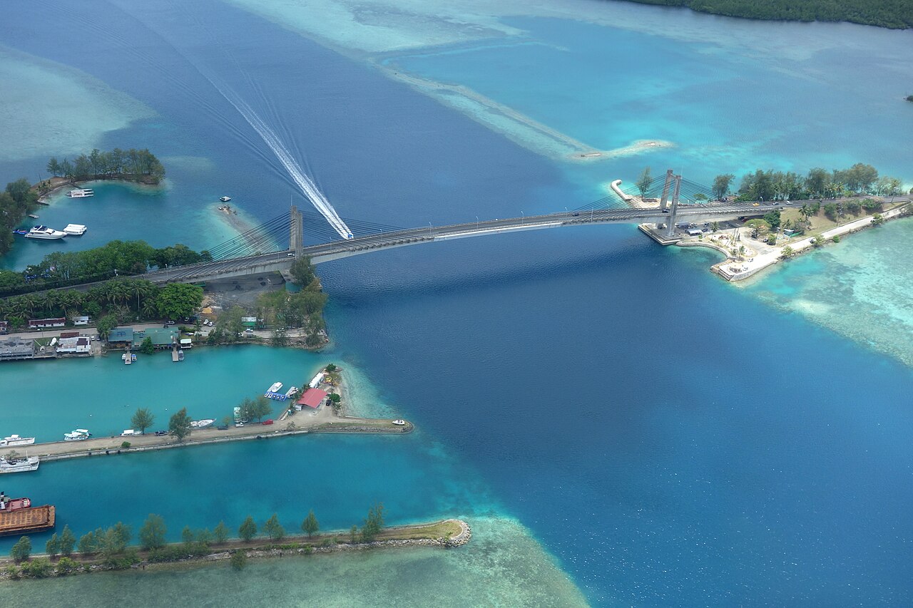
Koror–Babeldaob (K–B) Bridge
Palau · Built 1977 · retrofit 1996 · collapsed 1996 · 2 killed, 4 injured
At the time of construction the longest prestressed-concrete box-girder span in the world (241 m). Long-term creep and shrinkage caused the midspan sag to reach 1.6 m — far more than the design predicted. A 1996 retrofit added external post-tensioning cables and cast additional concrete at midspan; three months later the bridge collapsed. Investigations point to loss of prestress from creep interacting with the sequence in which new tendons were stressed against a deformed structure.
Engineering lessons
- Long-term creep of prestressed concrete is time-dependent and non-linear; single-value estimates are inadequate.
- Retrofit stressing sequence changes the load path — must be re-analysed on the current (deformed) geometry.
- Field measurement of camber and prestress loss should be part of any long-span PC bridge's inspection régime.
Case study
I-35W Mississippi River Bridge
Minneapolis, MN, USA · Built 1967 · collapsed 2007 · 13 killed, 145 injured
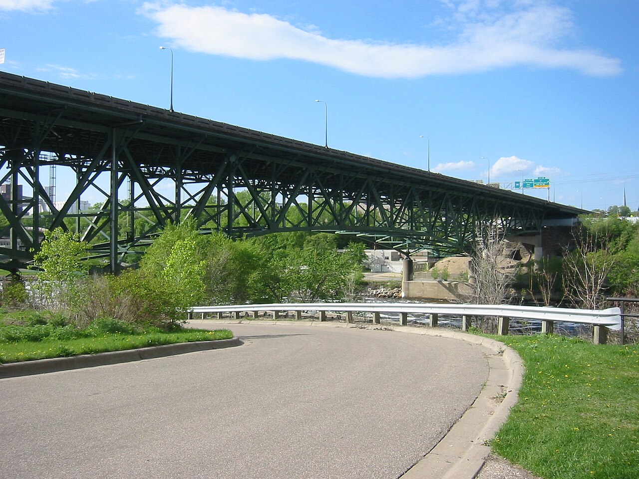
Although a service failure, the collapse is a construction-loading case study. The NTSB found that under-designed 12 mm gusset plates at node U10 had been operating near capacity for 40 years. On the day of failure, MnDOT was resurfacing the deck: 287 tonnes of construction aggregate, mixer trucks, and a paving machine were concentrated over the critical node, and the added dead load from prior overlays had never been recalculated against the original gussets.
Engineering lessons
- Every resurfacing / rehab must recalculate DL against the original design — γ_DW = 1.50 is not a decorative number.
- Non-redundant steel truss bridges (fracture-critical members) demand FCM inspection procedures — see Ch. 19.
- Construction staging on an in-service bridge is a design task, not a contractor detail.
- The collapse accelerated the FHWA gusset-plate re-evaluation programme across the U.S. inventory.
Case study
Hintze Ribeiro Bridge
Entre-os-Rios, Portugal · Built 1887 · collapsed 2001 · 59 killed
A 19th-century wrought-iron truss on stone piers over the Douro River. Decades of upstream sand mining had lowered the riverbed by 6 – 8 m, exposing and undermining the shallow spread footing of Pier 4. On a rainy March night the pier tilted, one span dropped, and a passenger bus and cars fell into the river. Not a construction failure per se, but a case study in how maintenance, inspection, and adjacent construction (dredging) interact with an old structure.
Engineering lessons
- Scour is the #1 cause of bridge collapse in the U.S. and worldwide — see Ch. 14.
- Underwater inspection of pier footings is mandatory for scour-critical bridges (NBIS Item 113).
- Adjacent human activity — sand mining, dredging, channel realignment — is a construction issue for existing bridges.
- Historic bridges need scour and inspection régimes matched to their actual foundation type, not the modern one.
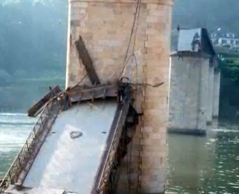
5. Failure mechanisms — a working vocabulary
Every case study above is an instance of one or two of the mechanisms below. Learn them as a vocabulary; when you inspect a bridge in construction, you are looking for these specific initiators.
Lateral-torsional buckling
Unbraced compression flange of a steel girder rolls sideways before the deck is composite.
Compression-chord buckling
Slender built-up compression member in a truss or cantilever buckles under growing dead load (Quebec 1907).
Connection fracture / bolt slip
Under-torqued or missing high-strength bolts let a friction connection slip; welded temporary detail cracks under fatigue.
Progressive collapse
One member fails, its share of load transfers to neighbours already at capacity, and the failure zips through the structure.
Falsework / shoring collapse
Shore towers settle, tilt, or lose their diagonal bracing during a concrete pour; the fresh deck comes down with them.
Launching instability
Incrementally launched or moved (SPMT) spans lose stability at a support transition or during jack synchronisation.
Temporary bearing / crib failure
Timber cribs crush, elastomeric temporary bearings roll out, or steel packers slip out during a jack-down.
Cable / tendon failure
PT cable de-tensions after grout failure or a stressing anchorage failure; catastrophic for cable-stayed and PT construction.
Crane overload / boom collapse
Erection crane operates beyond its rated capacity chart, or picks a girder at the wrong point and overturns.
Scour of temporary bent
Mid-river false bent loses its footing to overnight scour after a storm; span drops before crews return.
Loss of prestress from creep
Time-dependent shortening reduces cable force; deformed geometry invalidates the retrofit analysis (Koror–Babeldaob).
Gusset-plate under-strength
Load-path node designed on an old spec cannot carry cumulative overlay + construction load (I-35W).
The engineer's construction-phase checklist
- Draw the load path for every intermediate erection state, not just the finished bridge.
- Recompute stability of every unbraced member at every stage (girders before deck cures, cantilevers before closure pour).
- Treat contractor's temporary works (falsework, cribs, cranes, jack-downs) as designed elements with a stamped EOR review.
- Update dead load whenever geometry, materials, or sequence change — no exceptions.
- Establish written stop-work authority for the peer reviewer and the field inspector. Test it.
- Field-observe critical picks personally; do not delegate a pick with no back-up load path.
- When cracks, movements, or field observations do not match the model — close the road first, analyse second.
1.6 — The bridge engineer
Planner, architect, designer, constructor, facility manager
The bridge engineer is often involved with several or all aspects of a bridge's life — a situation unlike the building design profession, where the architect leads a team of specialists and the owner typically manages a single asset. In bridge work the engineer often controls type selection, aesthetics, and technical details; reviews shop drawings; and later inspects, load-rates, retrofits, and manages the same structure over decades. The owner — usually a state DOT or other public agency — is charged with management of an inventory of bridges through periodic inspections, rehabilitation, retrofit, and life-cycle deterioration modeling (Bridge Management Systems, BMS).
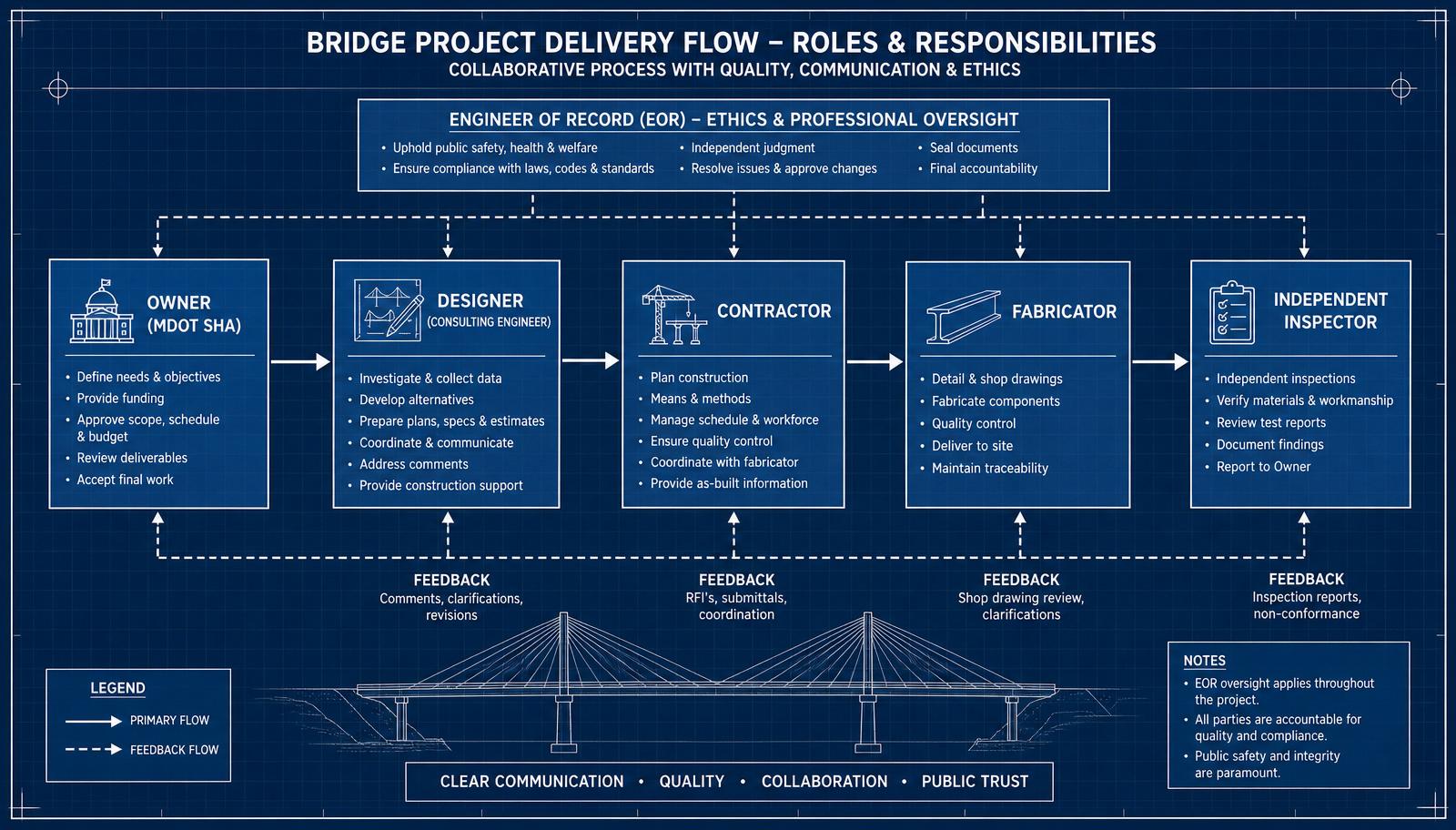
Ethics in practice
If a design or field observation places public safety at risk, the engineer's obligation is to disclose it — to the client and, when unresolved, to the licensing board. The 2007 I-35W collapse and the 2018 FIU-Sweetwater pedestrian bridge collapse both featured missed opportunities for a licensed engineer to invoke this obligation.
1.7 — System selection
Systems at a glance
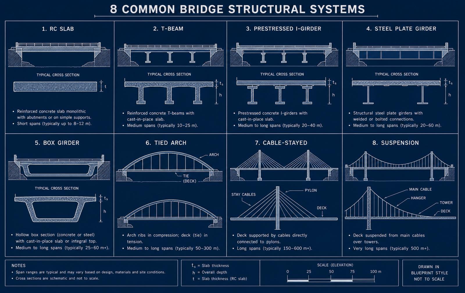
| System | Typical span range | Where it fits |
|---|---|---|
| Slab bridge (RC) | 0 – 40 ft | Short crossings, culvert replacements |
| RC / PC T-beam | 30 – 80 ft | Rural bridges, straightforward geometry |
| Prestressed I-girder | 60 – 160 ft | Workhorse for state highway bridges |
| Steel plate girder | 100 – 400 ft | Multi-span highway and interstate bridges |
| Segmental / box girder | 150 – 500 ft | Long spans, urban aesthetics |
| Tied arch | 250 – 900 ft | Long clear span, aesthetic gateway |
| Cable-stayed | 500 – 3,000 ft | Long spans over waterways |
| Suspension | 2,000 – 7,000 ft | Very long crossings |
Table 1.3 — Representative span ranges. Actual limits depend on materials, aesthetics, seismicity, hydraulics, and constructability.
1.8 — A Mid-Atlantic gateway
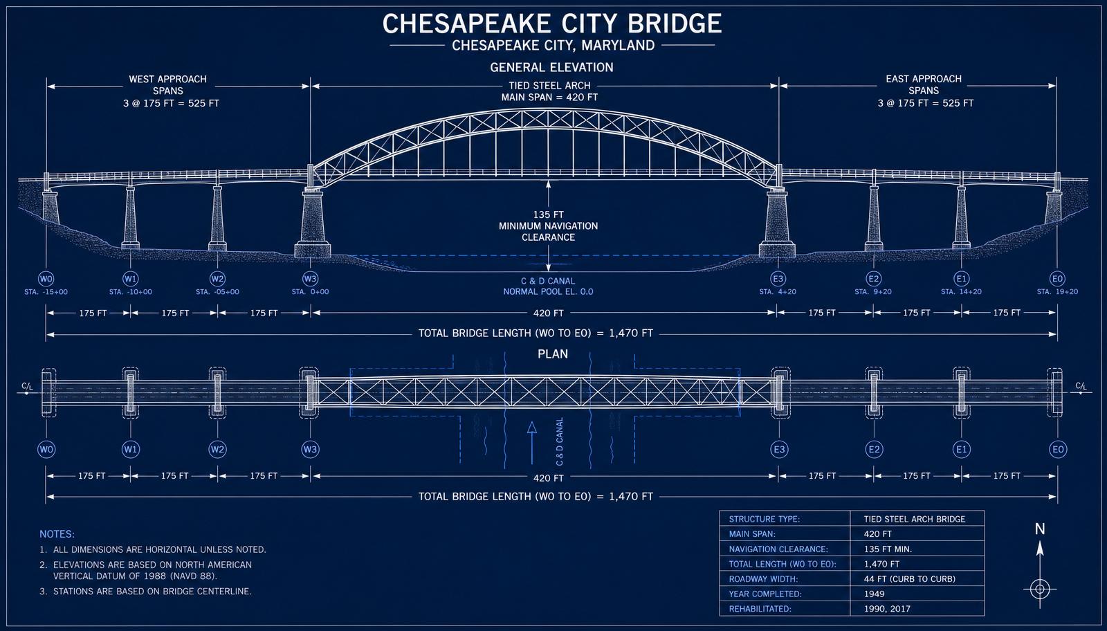
The Chesapeake City Bridge
Where U.S. Route 213 crosses the C&D Canal in Cecil County, Maryland, a 420-ft tied steel arch carries roadway traffic 135 ft above one of the busiest inland waterways in the United States. Opened in 1949 and rehabilitated multiple times since, it illustrates every theme of this course: navigation clearance, waterway hydraulics, long-span steel behavior, vessel-collision resistance of piers, deck fatigue, and periodic recoating for corrosion control. Its predecessor — a vertical-lift structure destroyed by a tanker collision in 1942 — is itself a formative moment in modern vessel-collision design (now codified in AASHTO LRFD §3.14 — Vessel Collision).
1.9 — Design life
What are we designing for?
AASHTO LRFD targets a 75-year design life for highway bridges with a reliability index β ≈ 3.5 at the strength limit state AASHTO LRFD §1.3.2. This does not mean the bridge is disposable at year 75 — it means the code-calibrated safety margins were established for that reference period. Preservation and rehabilitation extend service life well beyond 75 years — the average U.S. bridge is currently 44 years old (FHWA NBI, 2023).
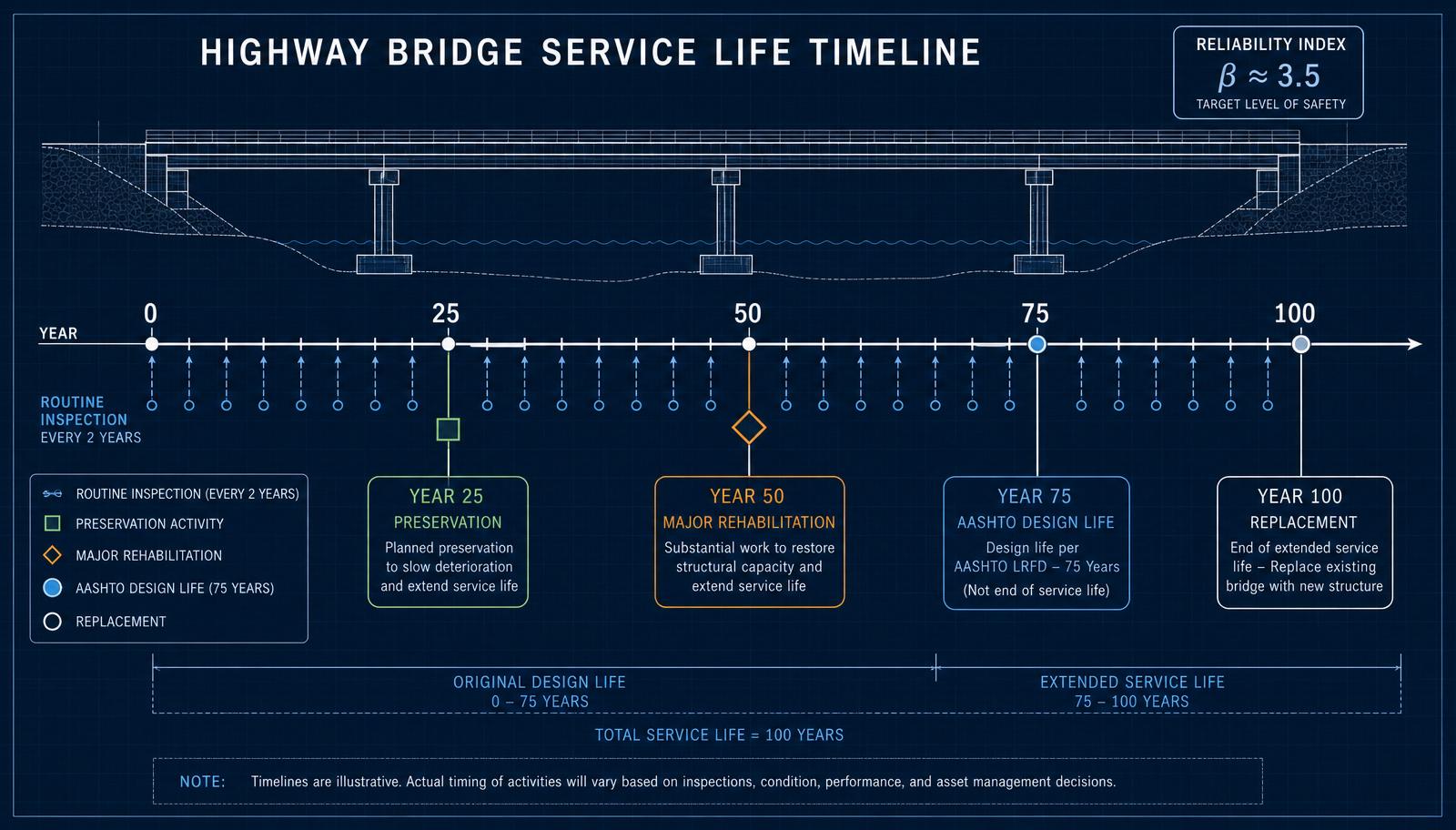
Design life is not service life
A 75-year design life sets the statistical horizon over which loads and resistances were calibrated. Actual service life depends on inspection, maintenance, preservation, and rehabilitation. Chapter 22 treats bridge management systems (BMS) — the tools MDOT SHA and other owners use to allocate lifecycle investment across a network of thousands of bridges.
1.10 — Design challenge
Recommend a bridge type for three sites
Open-ended design task
Recommend a bridge type — with justification — for each of the following:
- US 50 over a 90-ft-wide tributary of the Choptank River, Talbot County, MD. Two 12-ft lanes.
- Interstate 95 mainline over a 320-ft-wide freight-rail yard, Baltimore County, MD. Six lanes plus shoulders.
- Urban pedestrian crossing, 145-ft clear span, over MD Route 355, Bethesda. Aesthetics important; ADA-compliant approaches.
Deliverable: a single PDF (or DOCX) containing your sketch, span arrangement, material choice, cost/durability discussion, and one significant risk per site. Upload it below.
Submit your design challenge
Chapter 1 design challenge — bridge type selection for three Maryland sites
You must be signed in to upload a submission.
Sign in →Chapter summary
Key takeaways
- A bridge is the key element in a transportation system: it controls capacity, is the highest cost per mile, and if it fails, the system fails.
- U.S. bridge engineering evolved from stone arch → covered wood → metal truss → suspension → metal arch → RC/PC girder.
- Formal bridge specifications began after the 1876 Ashtabula failure; AASHTO LRFD (1994 → 10th Ed. 2024) is the modern governing standard.
- Silver, San Fernando, Sunshine Skyway, Mianus, Schoharie, and Cypress each rewrote a section of the AASHTO code.
- Most bridge failures actually occur during construction — stability of shoring and non-composite girders is the recurring theme.
- The bridge engineer plays every role from planner to facility manager. Ethics and public safety sit above all contract obligations.
- 75-year design life ≠ service life. Preservation and rehabilitation extend both, and lifecycle management is now a first-class discipline.
Section 3
Guided Practice
Complete the missing steps. Use Hints for AASHTO article pointers and setup logic before revealing the full step. Submit at the end to send your work to your instructor.
Guided Problem 1
A county highway carries a 120-ft simple-span steel I-girder bridge with a reinforced-concrete deck. ADT = 2,500 vpd, no rail traffic, no navigation clearance. Walk through classification and the specification that governs design.
Guided Problem 2
Total crossing length is 720 ft over a river with a 60-ft navigation channel centered on the crossing. You want approximately equal spans, no in-channel piers, and a prestressed-concrete I-girder deck.
Guided Problem 3
Owner compares a steel plate girder ($3.4M initial, $28k/yr maintenance, 75-yr life, deck overlay every 25 yr at $180k) against a PS concrete girder ($3.8M initial, $12k/yr maintenance, overlay every 40 yr at $180k). Discount rate 3%.
Guided Problem 4
An overpass replacement over a 4-lane interstate. Traffic must remain open, girder depth is limited to 4 ft, and the shoulder-to-shoulder width is 88 ft.
Section 4
Independent Practice
Every problem randomizes its inputs. Work each step, submit for immediate feedback, request new values to practice again.
Practice 1
Practice 2
Practice 3
Practice 4
Practice 5
Practice 6
Practice 7
Practice 8
Practice 9
Practice 10
Practice 11
Practice 12